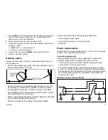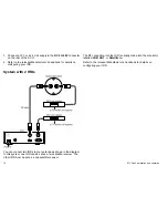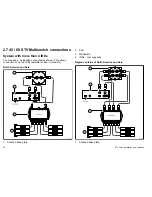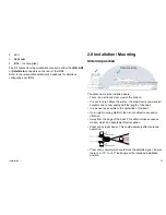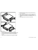
4. Put the NMEA OUT wire (yellow in the illustration) and ground
wire into the connector block with the corresponding GPS
antenna wires, as in the illustration.
5. Secure all connections in the connector block.
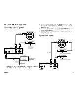
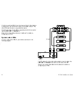
6. Connect and secure the free end of the additional cable in the 2
pin plug, so that:
i.
NMEA OUT (+) connects to pin 1.
ii. Ground (-) connects to pin 2.
7. Connect the 2 pin plug to
NMEA
on the rear of the ACU.
8. Switch on the STV system.
Routing cables
Cables must be routed correctly, to maximize performance and
prolong cable life.
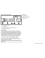
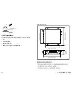
• Do NOT bend cables excessively. Wherever possible, ensure a
minimum bend radius of 100 mm.
Minimum bend of cable
100 mm (4 in) radius
Minimum bend
200 mm (8 in)
diameter
• Protect all cables from physical damage and exposure to heat.
Use trunking or conduit where possible. Do NOT run cables
through bilges or doorways, or close to moving or hot objects.
• Secure cables in place using tie-wraps or lacing twine. Coil any
extra cable and tie it out of the way.
• Where a cable passes through an exposed bulkhead or deckhead,
use a suitable watertight feed-through.
• Do NOT run cables near to engines or fluorescent lights.
Always route data cables as far away as possible from:
• other equipment and cables,
• high current carrying ac and dc power lines,
• antennae.
Power requirements
A Raymarine STV system needs either a 12 V dc or 24 V dc power
supply. This is connected into the ACU.
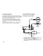
Grounding requirements
These grounding requirements are applicable for Raymarine
equipment supplied with a separate drain wire or screen.
•
The product power cable drain conductor (screen) must be
connected to a common ground point.
• It is recommended that the common ground point is a bonded
ground, i.e. with the ground point connected to battery negative,
and situated as close as possible to the battery negative terminal.
If a bonded ground system is not possible, a non-bonded RF
ground may be used.
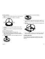
Bonded ground system (preferred)
D
1
1
7
0
9
-1
1
2
4
3
Installation
15


