


Chapter 1: ST70 Overview
3
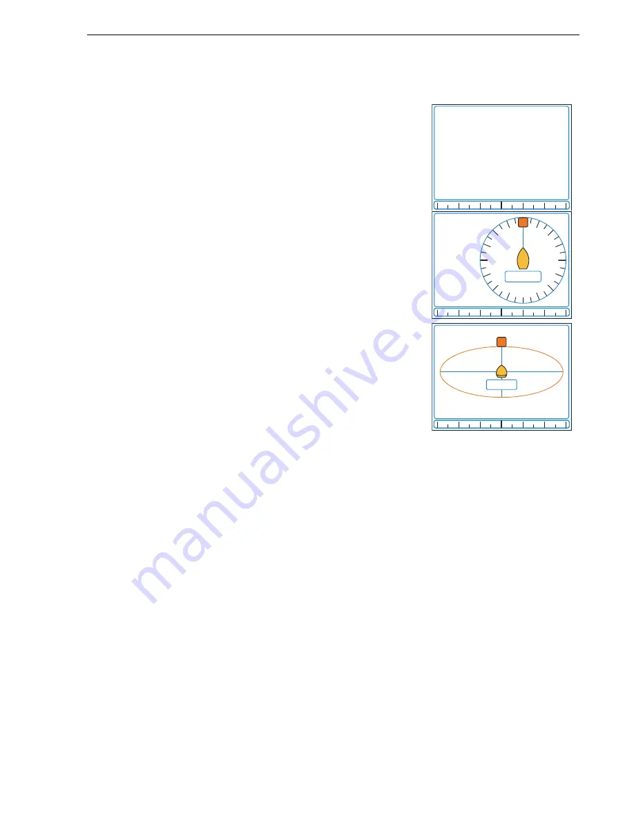
Auto mode
The ST70 Pilot can display current pilot data in one of three ways:
•
Heading
•
2D - Compass rose
•
3D - Isometric
Refer to
Section 3.3, Pilot view
.
1.3 Operating principles
The ST70 Pilot has two main modes of operation: Standby and Auto.
With the ST70 in Standby, the helm is free for manual steering and all setup functions
and calibrations can be performed. These settings are stored in the Course
Computer.
When in Auto mode, manual steering is not possible and the autopilot drives the helm.
First use after installation
When the ST70 Pilot controller is first switched on after installation it will require
commissioning.
Details of how to set these values and commission the Pilot are given in the
ST70
Autopilot Controller/SmartPilot X Commissioning Instructions
.
Note:
The values set during initial setup can be changed subsequently via the Main Menu.
Normal operation
Detailed operating instructions are given in the
ST70 Pilot Operating Guide
.
Mag
225
D
10931-1
M
W
E
S
N
SOG KTS
14.8
Depth M
6.2
TWS KTS
19.1
D10935-1
M
SOG KTS
14.8
Depth M
6.2
TWS KTS
19.1
N
D10930-1
Summary of Contents for ST70 Instrument
Page 1: ...ST70 Autopilot Controller User Reference Guide Document reference 81288 2 Date May 2010 ...
Page 2: ...ii ...
Page 26: ...18 ST70 Pilot Controller Reference Guide ...
Page 42: ...34 ST70 Pilot Controller Reference Guide ...
Page 50: ...42 ST70 Pilot Controller Reference Guide ...
Page 54: ...46 ...
Page 56: ...48 ST70 Pilot Controller Reference Guide ...


