background image

38

3.9 Rudder reference 

The SPX Solenoid requires a rudder reference to function correctly and is sup-
plied with a unit.

The SPX 30 is supplied with a rudder reference unit to provide maximum perfor-
mance. 

The SPX 10 does not require a rudder reference and is not supplied with one. 
However if the SPX 10 is being used with an extreme performance boat, the addi-
tion of a rudder reference may provide enhanced performance.

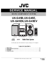
To mount and connect the rudder reference (if applica-

ble)

Fit the rudder reference using the instructions supplied with it. 

Route the cable back to the SPX SmartPilot.

Connect Rudder sensor to RUDDER terminal.

D10462-1

Course computer

POWER, 15 AMP

12V

24V

FLUXGATE

RUDDER

CLUTCH

S

POWER

 Cable, X metres (XX ft)

Rudder sensor

Screen

Red

Blue

Green

87072-2.book  Page 38  Thursday, November 22, 2007  8:43 AM

Summary of Contents for SPX 30

Page 1: ...SPX SmartPilot System Installation Guide SPX 10 SPX 30 SPX Solenoid Document reference 87072 2 Date November 2007...

Page 2: ...2...

Page 3: ...18 Required additional components 20 Optional additional components 20 3 2 Cable connection points and fuses 20 3 3 Autopilot controller 24 3 4 Drive unit 25 Clutch 26 3 5 Power and drive cables 27 C...

Page 4: ...ii...

Page 5: ...ded Failure to do so could result in personal injury damage to your boat and or poor product performance Before you install the SPX SmartPilot system check that individual components are the correct v...

Page 6: ...art does not have a separate battery Use Raymarine specified cables Do not cut or extend cables unless doing so is detailed in the installation manual Remember Where constraints on the installation pr...

Page 7: ...instructions Product disposal Waste Electrical and Electronic WEEE Directive The WEEE Directive requires the recycling of waste electrical and electronic equipment Whilst the WEEE Directive does not a...

Page 8: ...iv...

Page 9: ...e Autopilot system components on page 18 Installation When you have planned your system work through the following installation tasks in order referring to the appropriate section of this guide and yo...

Page 10: ...ne com 1 3 Further assistance Comprehensive customer support is available online and by telephone www raymarine com In the Customer Service area you will find Frequently Asked Questions FAQs Servicing...

Page 11: ...anying documents Document Part number SPX System Installation Guide this document Professional installers should use this guide to ensure safe and effective set up of an SPX SmartPilot system 87072 1...

Page 12: ...4...

Page 13: ...These components are linked logically as shown below 2 2 Data systems Data cables carry data and power to the autopilot controller instruments and onboard electronics such as GPS or chartplotter The S...

Page 14: ...tions There are restrictions on cable lengths power location and the number of components you may connect to a SeaTalkng system For complete information on SeaTalkng connectivity refer to the SeaTalkn...

Page 15: ...backbone using a plug in cable sup plied Instruments can be connected via spur cables or daisy chained together on a bus The SeaTalkng backbone cable is available as part of a standard kit Optional c...

Page 16: ...e simplest type of SeaTalkng system has a single SeaTalkng bus including one controller and several instruments D10436 1 ST70 controller ST70 instrument SeaTalkng backbone cable SeaTalkng bus SmartPil...

Page 17: ...pilot controller which repeats autopilot information The second controller is also connected to the backbone using a spur cable D10437 1 SeaTalkng backbone cable SeaTalkng SeaTalkng SeaTalkng SmartPi...

Page 18: ...ckbone is powered separately or if you are running an NMEA 2000 compliant system the SeaTalkng switch above the SeaTalkng terminal on the SPX SmartPilot must be moved to the OFF position D10465 1 ST70...

Page 19: ...ilot A SeaTalk based network does not have a central backbone cable Connector blocks are used to connect different parts of the system ST6002 controller ST60 depth instrument SeaTalk cable ST60 speed...

Page 20: ...lk system has a single SeaTalk bus including one controller and several instruments D10435 1 SeaTalk cable SeaTalk SeaTalk SeaTalk instrument SeaTalk instrument SeaTalk instrument SmartPilot controlle...

Page 21: ...your system which repeats autopilot information If you are using two control units we recommend they are connected to separate SeaTalk terminals on the SPX SmartPilot SeaTalk SeaTalk SeaTalk instrumen...

Page 22: ...V power supply to each end of the data bus ring main style Connect the SeaTalk bus as normal Connect a second SeaTalk cable to the SmartPilot and route it to the far end of the SeaTalk bus For the sec...

Page 23: ...Most Raymarine equipment will connect to your data system via SeaTalkng or SeaTalk except for A series which connects via NMEA 0183 Other manufacturers equipment connects via NMEA cabling Instrument S...

Page 24: ...ture additions or maintenance of the system The diagram should include Location of all components See EMC installation guidelines on page vi for condi tions that may affect the location of specific co...

Page 25: ...bling Schematic diagram detailing autopilotsystem location and connections including connections to existing equipment Refer to this diagram at each step of the instal lation process You should also c...

Page 26: ...The SPX 10 is designed to operate without a rudder reference unit In a small percentage of applications such as extremely high performance power boats you may find slightly en hanced performance with...

Page 27: ...ad self tapping screw x 3 No 8 x 3 4 inch csk head self tapping screw x 2 M6 stud M6 nut x2 Ball joint cap x2 Ball joint Rudder mounting assembly Cable tie small x10 Cable tie large x5 SeaTalkng 5 way...

Page 28: ...Cable connection points and fuses Cable connection points on the SPX 10 SPX 30 and SPX Solenoid vary slightly Throughout the following sets of instructions refer to the diagrams below to see the locat...

Page 29: ...lutch outputs Power fuse 40 A SeaTalkng power switch Clutch voltage switch RF ground connection GROUND 3029 632 E POWER POWER 15 AMP 12V OFF ON 24V FLUXGATE RUDDER BYPASS FAULT SLEEP FAULT 3 AMP 3 AMP...

Page 30: ...et automatically when the problem is rectified Spare standard automotive blade fuses are supplied with your SPX SmartPilot and are easily available Your Raymarine dealer can also provide a replacement...

Page 31: ...Chapter 3 Installation 23 D10448 1 MOUNT VERTICALLY 62 5 mm 2 45 in 284 mm 11 2 in 208 mm 8 2 in...

Page 32: ...compatible with the SPX SmartPilot To mount the autopilot controller Follow the installation instructions supplied with the autopilot controller Do not secure tightly until the data cables are connec...

Page 33: ...om the helm position through a chain and sprocket e g cable and rod Refer to the following table for drive unit compatibility with the SPX SmartPilot SPX SmartPilot Supply voltage Drive unit compatibi...

Page 34: ...V clutch move the clutch fuse switch on the SPX SmartPilot to the right Do not confuse the operating voltage of the clutch with the voltage used on the boat To mount the drive unit Fit the drive unit...

Page 35: ...in doubt use a heavier gauge cable You need to supply two lengths of power cable 1 Distribution panel to SPX SmartPilot 2 SPX SmartPilot to drive unit Select the appropriate type of power cable for ea...

Page 36: ...UTPUTS terminal Connect the drive to the DRIVE CLUTCH OUTPUTS Motor phasing is determined during commissioning refer to separate commissioning guide for further information Type 3 drive 12 V X30 up to...

Page 37: ...V 24V RUDDER CLUTCH POWER B MOTOR A Red Blue D10455 1 Power supply Red Black Without clutch With clutch With clutch Fuse or circuit breaker Drive unit Distribution panel Course computer Power Motor ca...

Page 38: ...3029 63 POWER SOLENOID SOLENOID A B Solenoid valves diodes across spool valves SPX SmartPilot solenoid connections Return cables Diodes Electronic steering or jog lever If electronic steering or jog l...

Page 39: ...ound Using the supplied yellow 1 4 inch female spade connector connectthe earthing braid to the RF GND terminal on the SPX SmartPilot Connect the other end of the earth strap to a dedicated earthing p...

Page 40: ...SeaTalkng backbone is powered separately or if you are run ning an NMEA 2000 compliant system the SeaTalkng switch above the SeaTalkng terminal on the SPX SmartPilot should be moved to the OFF positi...

Page 41: ...ng backbone cable or to an instru ment For detailed information refer to your autopilot controller installation guide and the SeaTalkng Reference Manual D10515 1 SeaTalkng T piece SeaTalkng 5 way conn...

Page 42: ...er end of the SeaTalk cable to a 3 way terminal block or other suitable connector on the system Note If you are supplying power separately to the SeaTalk bus do NOT connect the red wire at the SPX Sma...

Page 43: ...lation guide Connecting a SeaTalk controller Note If the controller is to be the primary controller we recommend a direct connection to the system rather than daisy chaining the controller to an instr...

Page 44: ...ird party equipment refer to the manufacturer s instructions for installation and cable details You must not connect more than one piece of equipment to each SPX computer NMEA input You may do any of...

Page 45: ...d instructions refer to the separate installation information supplied with the compass To mount the compass Fit the fluxgate compass using the installation instructions supplied with the compass payi...

Page 46: ...However if the SPX 10 is being used with an extreme performance boat the addi tion of a rudder reference may provide enhanced performance To mount and connect the rudder reference if applica ble Fit...

Page 47: ...arms from all controllers On large or noisy boats you can fit a Raymarine external alarm part number E26033 connected through E85001 interface box as a high volume audible repeater 3 12 Wind vane sail...

Page 48: ...alkng connections and terminators SeaTalk If you are using a SmartPilot controller ST6002 ST7002 or ST8002 and it does not power up Hold down the Display button for 1 second If the SPX SmartPilot and...

Page 49: ...cables to the SPX SmartPilot computer with cable ties as shown below 3 15Commissioning The autopilot must be commissioned prior to use For new systems this involves calibrating the system which is a...

Page 50: ...42...

Page 51: ...ID width height depth 307mm 12 1 in 195 mm 7 7 in 70 mm 2 8 in Weight X 10 X 30 X SOLENOID 1 1 kg 2 42 lbs 2 2 kg 4 85 lbs Inputs X 10 X30 X SOLENOID fluxgate compass rudder position sensor NMEA 0183...

Page 52: ...uts out puts See NMEA 0183 sentenceson page 45for information on NMEA 0183 received transmitted NMEA fast heading output X 10 X 30 X SOLENOID HDM 5 Hz 0 1 resolution Fuses Power Terminals SeaTalk Term...

Page 53: ...nce to waypoint waypoint number time GGA GLL latitude longitude time HDG HDM HDT heading MWV apparent wind angle apparent wind speed RMA courseoverground COG speedoverground SOG latitude lon gitude va...

Page 54: ...46...

Reviews: