Important:
To ensure power cables (including any extension) are of a sufficient gauge, ensure
that there is a continuous
minimum
voltage of
10.8 V dc
at the end of the cable where it enters
the product’s power connector, even with a fully flat battery at 11 V dc. (Do not assume that a flat
battery is at 0 V dc. Due to the discharge profile and internal chemistry of batteries, the current
drops much faster than the voltage. A “fully flat” battery still shows a positive voltage, even if it
doesn’t have enough current to power your device.)
Grounding
Ensure that you observe any additional grounding advice provided in the product’s documentation.
More information
It is recommended that best practice is observed in all vessel electrical installations, as detailed
in the following standards:
• BMEA Code of Practice for Electrical and Electronic Installations in Boats
• NMEA 0400 Installation Standard
• ABYC E-11 AC & DC Electrical Systems on Boats
• ABYC A-31 Battery chargers and Inverters
• ABYC TE-4 Lightning Protection
4.4 Handset station connection
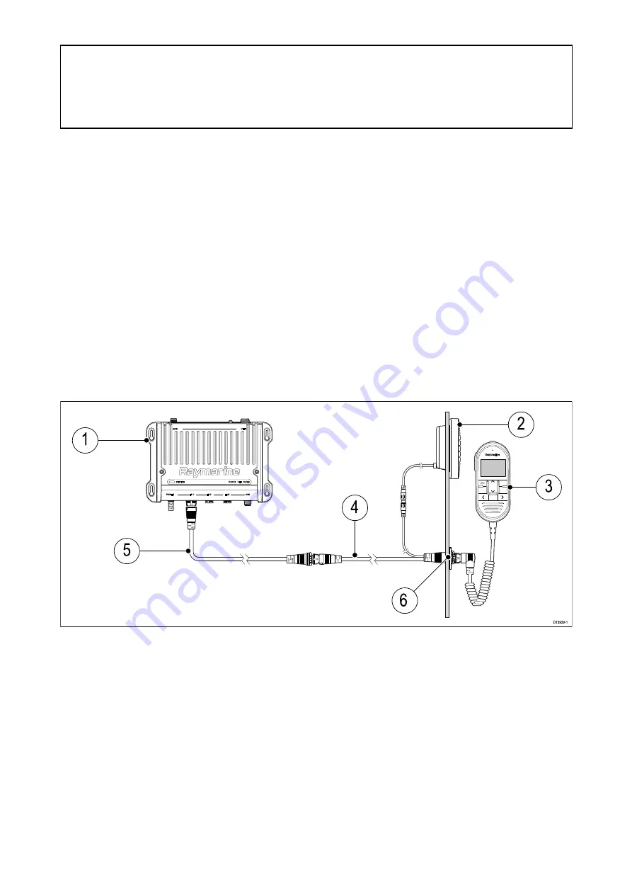
A Wired handset can be connected to each Handset station connection (HS 1 / HS 2). Your radio is
supplied with the equipment to create a full handset station (i.e.: Wired handset, Adaptor cable and
Passive speaker). Additional accessories can be purchased to create a second wired handset station.
1.
Base station
2. Passive speaker (1 x supplied and available as accessory: A80542)
3.
Wired handset (1 x supplied and available as accessory: A80289)
4.
Handset station adaptor cable with RCA Audio 400 mm (1.3 ft) (1 x supplied and available as
accessory: A80297)
5. Wired handset extension cable (Available optional accessories: A80290 – 5 m, A80291 – 10
m or 15 – A80292)
6. Panel mount fixings kit (1 x supplied and available as a Spare: R70438)
Connecting handsets and cables
Follow the steps below to connect handsets and extension cables together.
1. If fitted, unscrew and remove the dust cap from the relevant connector.
2. Ensure the cable connectors are correctly orientated, before insertion.
3. Ensure connectors are fully inserted, before locking..
54


