background image

6

Heading Sensor Owner’s Handbook

Although every effort has been taken to ensure that they will perform
under all conditions, it is important to understand what factors could
affect the operation of the product.

The guidelines given here describe the  conditions for optimum EMC
performance, but it is recognized that it may not be possible to meet all
of these conditions in all situations. To ensure the best possible
conditions for EMC performance within the constraints imposed by
any location, always ensure the maximum separation possible between
different items of electrical equipment.

For 

optimum

 EMC performance, it is recommended that 

wherever

possible

:

• Raymarine equipment and cables connected to it are:

At least 3 ft (1 m) from any equipment transmitting or cables
carrying radio signals e.g. VHF radios, cables and antennas. In
the case of SSB radios, the distance should be increased to 7 ft
(2 m).

More than 7 ft (2 m) from the path of a radar beam.  A radar
beam can normally be assumed to spread 20 degrees above and
below the radiating element.

• The equipment is supplied from a separate battery from that used for

engine start. Voltage drops below 10 V in the power supply to our
products, and starter motor transients, can cause the equipment to
reset.  This will not damage the equipment, but may cause the loss of
some information and may change the operating mode.

• Raymarine specified cables are used. Cutting and rejoining these

cables can compromise EMC performance and must be avoided
unless doing so is detailed in the installation manual.

• If a suppression ferrite is attached to a cable, this ferrite should not

be removed. If the ferrite needs to be removed during installation it
must be reassembled in the same position.

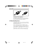
Suppression Ferrites

The following illustration shows typical cable suppression ferrites used
with Raymarine equipment. Always use the ferrites supplied by
Raymarine.

124_3c03.p65

09/05/01, 11:30

6

Summary of Contents for Heading Sensor

Page 1: ...Heading Sensor Owner s Handbook Document number 81124_3 Date 1stMay2001 124_3cov p65 09 05 01 11 29 1 ...

Page 2: ...Copyright Raymarine Limited 2001 124_3cov p65 09 05 01 11 29 2 ...

Page 3: ...ineenvironment ThedesignandmanufactureofRaymarineequipmentandaccessories conformtotheappropriateElectromagneticCompatibility EMC standards butcorrectinstallationisrequiredtoensurethatperformance isnotcompromised Handbook information Tothebestofourknowledge theinformationinthishandbookwas correctwhenitwenttopress However theRaymarinepolicyof continuous productimprovementmaychangeproductspecificatio...

Page 4: ...ii HeadingSensorOwner sHandbook 124_3pre p65 09 05 01 11 29 2 ...

Page 5: ...e Fault Finding 3 2 1 Servicing and Safety 3 2 2 Maintenance 3 2 3 Fault Finding 4 Assistance 4 Chapter 3 Installation 5 3 1 Before you Begin 5 Components 5 Basic Installation Tools 5 EMC Installation Guidelines 5 Suppression Ferrites 6 Connections to Other Equipment 7 3 2 Siting the Heading Sensor 7 3 3 Installation Procedure 8 3 4 Connection Procedure 9 124_3pre p65 09 05 01 11 29 3 ...

Page 6: ...SensorOwner sHandbook Chapter 4 Calibration 11 4 1 Introduction 11 EMC Conformance 11 4 2 Continuous Deviation Correction 11 4 3 Heading Alignment 12 Heading Sensor Specification 15 124_3pre p65 09 05 01 11 29 4 ...

Page 7: ...andbookcontainsimportantinformationontheinstallation calibrationandmaintenanceofyourHeadingSensor Pleasereadthe handbookthoroughly sothatyougetthebestresultsfromthisproduct 1 2 Description TheRaymarineHeadingSensorconsistsofanoil filledsphere suspendedinacustombuilt swingbracket togetherwithassociated electronics TheHeadingSensortransmitsmagneticcompassheadingdatato equipmentthatisNMEA0183compatib...

Page 8: ...2 HeadingSensorOwner sHandbook 124_3c01 p65 09 05 01 11 29 2 ...

Page 9: ...cefromyourRaymarine equipment guidelinesaregivenintheinstallationinstructions to enableyoutoensureminimuminteractionbetweendifferentitems ofequipment i e ensureoptimumElectromagneticCompatibility EMC AlwaysreportanyEMC relatedproblemtoyournearestRaymarine dealer Weusesuchinformationtoimproveourqualitystandards Insomeinstallations itmaynotbepossibletopreventthe equipmentfrombeingaffectedbyexternali...

Page 10: ...tion Nocompassheadingdataavailable Check that the cable connecting the Heading Sensor to the NMEA instrumentorsystemisfirmlyattached and undamaged The compass heading displayed on Heading Sensor has not been linearised theassociatedinstrumentisnotthe sameastheship scompass Linearisation procedure unsuccessful Move the Heading Sensor to a new location and try again Assistance Ifyoustillhaveaproblem...

Page 11: ...tandard components HeadingSensor Swing bracket Selftappingscrews 4 6ft 2m cable withmoldedHeadingSensorplugononeend IfyouareinstallingtheHeadingSensoratadistancefromanNMEA instrumentorsystem youmayalsoneeda16 25ft 5m NMEA accessorycable Basic InstallationTools Crossheadscrewdriver Electric handdrill 1mm 0 39in drillbit EMC Installation Guidelines AllRaymarineequipmentandaccessoriesaredesignedtothe...

Page 12: ...ofSSBradios thedistanceshouldbeincreasedto7 ft 2 m Morethan7ft 2m fromthepathofaradarbeam Aradar beamcannormallybeassumedtospread20degreesaboveand belowtheradiatingelement Theequipmentissuppliedfromaseparatebatteryfromthatusedfor enginestart Voltagedropsbelow10 Vinthepowersupplytoour products andstartermotortransients cancausetheequipmentto reset Thiswillnotdamagetheequipment butmaycausethelossof ...

Page 13: ...ticalorhorizontalbulkhead preferablyforwardfacing awayfromlargeferrousobjectssuchasthe engineandothermagneticdevices Ifyouhaveanydoubtsaboutthemagneticsuitabilityofachosen location attachahandbearingcompasstothechosensiteandthenturn yourvesselthrough360 Differencesbetweenthehand bearing compassandtheboat scompassshouldnotexceed10 onanyheading TheHeadingSensorshouldbepositionedascloseaspossibletoth...

Page 14: ...adingSensor 1 HoldtheHeadingSensormountingbracket 4 againstthe selectedbulkhead 2 OutlinethefourfixingholesintheHeadingSensormounting bracket 4 3 Drillfourpilotholesfortheself tappingscrews 4 SecuretheHeadingSensormountingbracket 4 tothebulkhead usingthefourself tappingscrews 3 provided Theembossed arrowonthebackofthebracketmustbepointingskywards Note The Heading Sensor must be within 10 of the ve...

Page 15: ...ading Sensor mounting bracket 6 PasstheAllenbolt 2 throughtheapertureinthetopofthe HeadingSensormountingbracket 4 andtightenusingtheAllen keysupplied Note You may need to loosen this later to adjust the Heading Sensor alignment as described in Chapter 4 Calibration 3 4 Connection Procedure ToconnectyourHeadingSensortoanNMEA0183compatible instrument suchasaXXRadar 1 Plugthe6ft 2m HeadingSensorcable...

Page 16: ...MEA0183compatible equipment todeterminethecorrectpinconnectionsfortheheading sensorinput Forexample theconnectionsforaXXRadarareshown inthefollowingdiagram 5 12VDC Heading sensor 6 Ground Heading sensor 4 NMEA Heading sensor 3 NMEA Heading sensor 2 NMEA Navigation aid 1 NMEA Navigation aid D5507 1 Red Black Yellow 6 1 5 4 2 3 XX Radar J404 NMEA Chassis Connector viewed from the solder side of the ...

Page 17: ...singtheRaymarineHeading Sensor sContinuousDeviationCorrection TheHeadingSensor monitorsthedeviationcontinuouslyand iftherequiredconditionsare met updatesitscorrectiondata ThischapterdescribestheContinuousDeviationCorrectionprocedure andtheheadingalignmentprocedure EMC Conformance Alwayschecktheinstallationbeforegoingtoseatomakesurethatit isnotaffectedbyradiotransmissions enginestartingetc 4 2 Cont...

Page 18: ...ariationdataobtained 4 3 HeadingAlignment AfteryouhaveperformedtheContinuousDeviationCorrection procedure youshouldchecktheheadingalignment Youcandoso usingoneorbothofthefollowingtechniques Comparetheheadinginformationonyourdisplayinstrument such asaXXRadarorRayData withtheship smagneticcompassfor severalheadings Note Your magnetic compass must be accurate and should have been calibrated recently ...

Page 19: ...otatethesensorslightlyclockwise IftheHeadingSensor sreadingsaregreaterthantheactual readings rotatethesensorslightlyanti clockwise 3 Checktheheadingsagain andrepeatstep2ifrequired 4 Whentheheadingsmatch tightentheAllenbolttoholdthesensor initsnewposition 124_3c04 p65 09 05 01 11 30 13 ...

Page 20: ...14 HeadingSensorOwner sHandbook 124_3c04 p65 09 05 01 11 30 14 ...

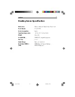
Page 21: ...Power Supply 10 to 16V DC Power Consumption 40mA Operating Temperature 10 Cto 70 C 14 Fto158 F Weight 450g 1 lb Compatability NMEA0183compatibleequipment Accuracy 0 5 Gimbal Range Pitch 33 Roll 45 Data Output NMEA HDM MagneticCompassHeading 10Hz HDG Headingonly 124_3spe p65 09 05 01 11 30 15 ...

Page 22: ...16 HeadingSensorInstallationManual 124_3spe p65 09 05 01 11 30 16 ...

Page 23: ...impellers impeller bearings and impeller shaft are specifically excluded from this Warranty Magnetrons Cathode Ray Tubes CRT TFT Liquid Crystal Displays LCD and cold cathode fluorescentlamps CCFL hailerhornsandtransducersarewarrantedfor1year 12monthsfromdate of sale These items must be returned to a Raymarine facility All costs associated with transducer replacement other than the cost of the tran...

Page 24: ...39 Ext 2333 or 1 603 881 5200 Ext 2333 Customer Support Telephone 44 0 23 9271 4713 Fax 44 0 23 9266 1228 Technical Support Telephone 1 800 539 5539 Ext 2444 or 1 603 881 5200 Ext 2444 Email techsupport raymarine com Email techsupport raymarine com Product Repair Center Telephone 1 800 539 5539 Ext 2118 Purchased from Purchase date Dealer address Installed by Installation date Commissioned by Comm...

Reviews: