background image

Document number: 84064-8

April 2001

Limited Warranty Certificate

Raymarine warrants each new Light Marine/Dealer Distributor Product to be of good materials and 
workmanship, and will repair or exchange any parts proven to be defective in material and 
workmanship under normal use for a period of 2 years/24 months from date of sale to end user, except 
as provided below.
Defects will be corrected by Raymarine or an authorized Raymarine dealer. Raymarine will, except 
as provided below, accept labor cost for a period of 2 years/24 months from the date of sale to end user. 
During this period, except for certain products, travel costs (auto mileage and tolls) up to 100 round 
trip highway miles (160 kilometres) and travel time of 2 hours, will be assumed by Raymarine only 
on products where proof of installation or commission by authorized service agents, can be shown.

Warranty Limitations

Raymarine Warranty policy does not apply to equipment which has been subjected to accident, abuse 
or misuse, shipping damage, alterations, corrosion, incorrect and/or non-authorized service, or 
equipment on which the serial number has been altered, mutilated or removed.
Except where Raymarine or its authorized dealer has performed the installation, it assumes no 
responsibility for damage incurred during installation.
This Warranty does not cover routine system checkouts or alignment/calibration, unless required by 
replacement of part(s) in the area being aligned.
A suitable proof of purchase, showing date, place, and serial number must be made available to 
Raymarine or authorized service agent at the time of request for Warranty service.
Consumable items, (such as: Chart paper, lamps, fuses, batteries, styli, stylus/drive belts, radar mixer 
crystals/diodes, snap-in impeller carriers, impellers, impeller bearings, and impeller shaft) are 
specifically excluded from this Warranty.
Magnetrons, Cathode Ray Tubes (CRT), TFT Liquid Crystal Displays (LCD) and cold cathode 
fluorescent lamps (CCFL), hailer horns and transducers are warranted for 1 year/12 months from date 
of sale. These items must be returned to a Raymarine facility.
All costs associated with transducer replacement, other than the cost of the transducer itself, are 
specifically excluded from this Warranty.
Overtime premium labor portion of services outside of normal working hours is not covered by this 
Warranty.
Travel cost allowance on certain products with a suggested retail price below $2500.00 is not 
authorized. When/or if repairs are necessary, these products must be forwarded to a Raymarine 
facility or an authorized dealer at owner’s expense will be returned via surface carrier at no cost to the 
owner.
Travel costs other than auto mileage, tolls and two (2) hours travel time, are specifically excluded on 
all products. Travel costs which are excluded from the coverage of this Warranty include but are not 
limited to: taxi, launch fees, aircraft rental, subsistence, customs, shipping and communication 
charges etc. Travel costs, mileage and time, in excess to that allowed must have prior approval in 
writing. 
TO THE EXTENT CONSISTENT WITH STATE AND FEDERAL LAW:
(1) THIS WARRANTY IS STRICTLY LIMITED TO THE TERMS INDICATED HEREIN, AND 
NO OTHER WARRANTIES OR REMEDIES SHALL BE BINDING ON RAYMARINE 
INCLUDING WITHOUT LIMITATION ANY WARRANTIES OF MERCHANTABLE OR 
FITNESS FOR A PARTICULAR PURPOSE.
(2) Raymarine shall not be liable for any incidental, consequential or special (including punitive or 
multiple) damages.
All Raymarine products sold or provided hereunder are merely aids to navigation. It is the 
responsibility of the user to exercise discretion and proper navigational skill independent of any 
Raymarine equipment.

84064_8.fm  Page 1  Monday, April 9, 2001  4:42 PM

Summary of Contents for Heading Sensor

Page 1: ...Heading Sensor Owner s Handbook Document number 81124_3 Date 1stMay2001 124_3cov p65 09 05 01 11 29 1 ...

Page 2: ...Copyright Raymarine Limited 2001 124_3cov p65 09 05 01 11 29 2 ...

Page 3: ...ineenvironment ThedesignandmanufactureofRaymarineequipmentandaccessories conformtotheappropriateElectromagneticCompatibility EMC standards butcorrectinstallationisrequiredtoensurethatperformance isnotcompromised Handbook information Tothebestofourknowledge theinformationinthishandbookwas correctwhenitwenttopress However theRaymarinepolicyof continuous productimprovementmaychangeproductspecificatio...

Page 4: ...ii HeadingSensorOwner sHandbook 124_3pre p65 09 05 01 11 29 2 ...

Page 5: ...e Fault Finding 3 2 1 Servicing and Safety 3 2 2 Maintenance 3 2 3 Fault Finding 4 Assistance 4 Chapter 3 Installation 5 3 1 Before you Begin 5 Components 5 Basic Installation Tools 5 EMC Installation Guidelines 5 Suppression Ferrites 6 Connections to Other Equipment 7 3 2 Siting the Heading Sensor 7 3 3 Installation Procedure 8 3 4 Connection Procedure 9 124_3pre p65 09 05 01 11 29 3 ...

Page 6: ...SensorOwner sHandbook Chapter 4 Calibration 11 4 1 Introduction 11 EMC Conformance 11 4 2 Continuous Deviation Correction 11 4 3 Heading Alignment 12 Heading Sensor Specification 15 124_3pre p65 09 05 01 11 29 4 ...

Page 7: ...andbookcontainsimportantinformationontheinstallation calibrationandmaintenanceofyourHeadingSensor Pleasereadthe handbookthoroughly sothatyougetthebestresultsfromthisproduct 1 2 Description TheRaymarineHeadingSensorconsistsofanoil filledsphere suspendedinacustombuilt swingbracket togetherwithassociated electronics TheHeadingSensortransmitsmagneticcompassheadingdatato equipmentthatisNMEA0183compatib...

Page 8: ...2 HeadingSensorOwner sHandbook 124_3c01 p65 09 05 01 11 29 2 ...

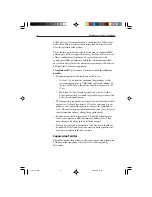
Page 9: ...cefromyourRaymarine equipment guidelinesaregivenintheinstallationinstructions to enableyoutoensureminimuminteractionbetweendifferentitems ofequipment i e ensureoptimumElectromagneticCompatibility EMC AlwaysreportanyEMC relatedproblemtoyournearestRaymarine dealer Weusesuchinformationtoimproveourqualitystandards Insomeinstallations itmaynotbepossibletopreventthe equipmentfrombeingaffectedbyexternali...

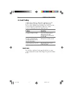
Page 10: ...tion Nocompassheadingdataavailable Check that the cable connecting the Heading Sensor to the NMEA instrumentorsystemisfirmlyattached and undamaged The compass heading displayed on Heading Sensor has not been linearised theassociatedinstrumentisnotthe sameastheship scompass Linearisation procedure unsuccessful Move the Heading Sensor to a new location and try again Assistance Ifyoustillhaveaproblem...

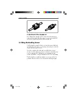
Page 11: ...tandard components HeadingSensor Swing bracket Selftappingscrews 4 6ft 2m cable withmoldedHeadingSensorplugononeend IfyouareinstallingtheHeadingSensoratadistancefromanNMEA instrumentorsystem youmayalsoneeda16 25ft 5m NMEA accessorycable Basic InstallationTools Crossheadscrewdriver Electric handdrill 1mm 0 39in drillbit EMC Installation Guidelines AllRaymarineequipmentandaccessoriesaredesignedtothe...

Page 12: ...ofSSBradios thedistanceshouldbeincreasedto7 ft 2 m Morethan7ft 2m fromthepathofaradarbeam Aradar beamcannormallybeassumedtospread20degreesaboveand belowtheradiatingelement Theequipmentissuppliedfromaseparatebatteryfromthatusedfor enginestart Voltagedropsbelow10 Vinthepowersupplytoour products andstartermotortransients cancausetheequipmentto reset Thiswillnotdamagetheequipment butmaycausethelossof ...

Page 13: ...ticalorhorizontalbulkhead preferablyforwardfacing awayfromlargeferrousobjectssuchasthe engineandothermagneticdevices Ifyouhaveanydoubtsaboutthemagneticsuitabilityofachosen location attachahandbearingcompasstothechosensiteandthenturn yourvesselthrough360 Differencesbetweenthehand bearing compassandtheboat scompassshouldnotexceed10 onanyheading TheHeadingSensorshouldbepositionedascloseaspossibletoth...

Page 14: ...adingSensor 1 HoldtheHeadingSensormountingbracket 4 againstthe selectedbulkhead 2 OutlinethefourfixingholesintheHeadingSensormounting bracket 4 3 Drillfourpilotholesfortheself tappingscrews 4 SecuretheHeadingSensormountingbracket 4 tothebulkhead usingthefourself tappingscrews 3 provided Theembossed arrowonthebackofthebracketmustbepointingskywards Note The Heading Sensor must be within 10 of the ve...

Page 15: ...ading Sensor mounting bracket 6 PasstheAllenbolt 2 throughtheapertureinthetopofthe HeadingSensormountingbracket 4 andtightenusingtheAllen keysupplied Note You may need to loosen this later to adjust the Heading Sensor alignment as described in Chapter 4 Calibration 3 4 Connection Procedure ToconnectyourHeadingSensortoanNMEA0183compatible instrument suchasaXXRadar 1 Plugthe6ft 2m HeadingSensorcable...

Page 16: ...MEA0183compatible equipment todeterminethecorrectpinconnectionsfortheheading sensorinput Forexample theconnectionsforaXXRadarareshown inthefollowingdiagram 5 12VDC Heading sensor 6 Ground Heading sensor 4 NMEA Heading sensor 3 NMEA Heading sensor 2 NMEA Navigation aid 1 NMEA Navigation aid D5507 1 Red Black Yellow 6 1 5 4 2 3 XX Radar J404 NMEA Chassis Connector viewed from the solder side of the ...

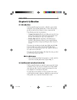
Page 17: ...singtheRaymarineHeading Sensor sContinuousDeviationCorrection TheHeadingSensor monitorsthedeviationcontinuouslyand iftherequiredconditionsare met updatesitscorrectiondata ThischapterdescribestheContinuousDeviationCorrectionprocedure andtheheadingalignmentprocedure EMC Conformance Alwayschecktheinstallationbeforegoingtoseatomakesurethatit isnotaffectedbyradiotransmissions enginestartingetc 4 2 Cont...

Page 18: ...ariationdataobtained 4 3 HeadingAlignment AfteryouhaveperformedtheContinuousDeviationCorrection procedure youshouldchecktheheadingalignment Youcandoso usingoneorbothofthefollowingtechniques Comparetheheadinginformationonyourdisplayinstrument such asaXXRadarorRayData withtheship smagneticcompassfor severalheadings Note Your magnetic compass must be accurate and should have been calibrated recently ...

Page 19: ...otatethesensorslightlyclockwise IftheHeadingSensor sreadingsaregreaterthantheactual readings rotatethesensorslightlyanti clockwise 3 Checktheheadingsagain andrepeatstep2ifrequired 4 Whentheheadingsmatch tightentheAllenbolttoholdthesensor initsnewposition 124_3c04 p65 09 05 01 11 30 13 ...

Page 20: ...14 HeadingSensorOwner sHandbook 124_3c04 p65 09 05 01 11 30 14 ...

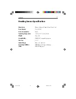
Page 21: ...Power Supply 10 to 16V DC Power Consumption 40mA Operating Temperature 10 Cto 70 C 14 Fto158 F Weight 450g 1 lb Compatability NMEA0183compatibleequipment Accuracy 0 5 Gimbal Range Pitch 33 Roll 45 Data Output NMEA HDM MagneticCompassHeading 10Hz HDG Headingonly 124_3spe p65 09 05 01 11 30 15 ...

Page 22: ...16 HeadingSensorInstallationManual 124_3spe p65 09 05 01 11 30 16 ...

Page 23: ...impellers impeller bearings and impeller shaft are specifically excluded from this Warranty Magnetrons Cathode Ray Tubes CRT TFT Liquid Crystal Displays LCD and cold cathode fluorescentlamps CCFL hailerhornsandtransducersarewarrantedfor1year 12monthsfromdate of sale These items must be returned to a Raymarine facility All costs associated with transducer replacement other than the cost of the tran...

Page 24: ...39 Ext 2333 or 1 603 881 5200 Ext 2333 Customer Support Telephone 44 0 23 9271 4713 Fax 44 0 23 9266 1228 Technical Support Telephone 1 800 539 5539 Ext 2444 or 1 603 881 5200 Ext 2444 Email techsupport raymarine com Email techsupport raymarine com Product Repair Center Telephone 1 800 539 5539 Ext 2118 Purchased from Purchase date Dealer address Installed by Installation date Commissioned by Comm...

Reviews: