


38
Raymarine H6 - System Installation Manual
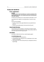
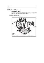
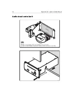
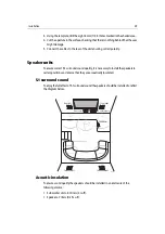
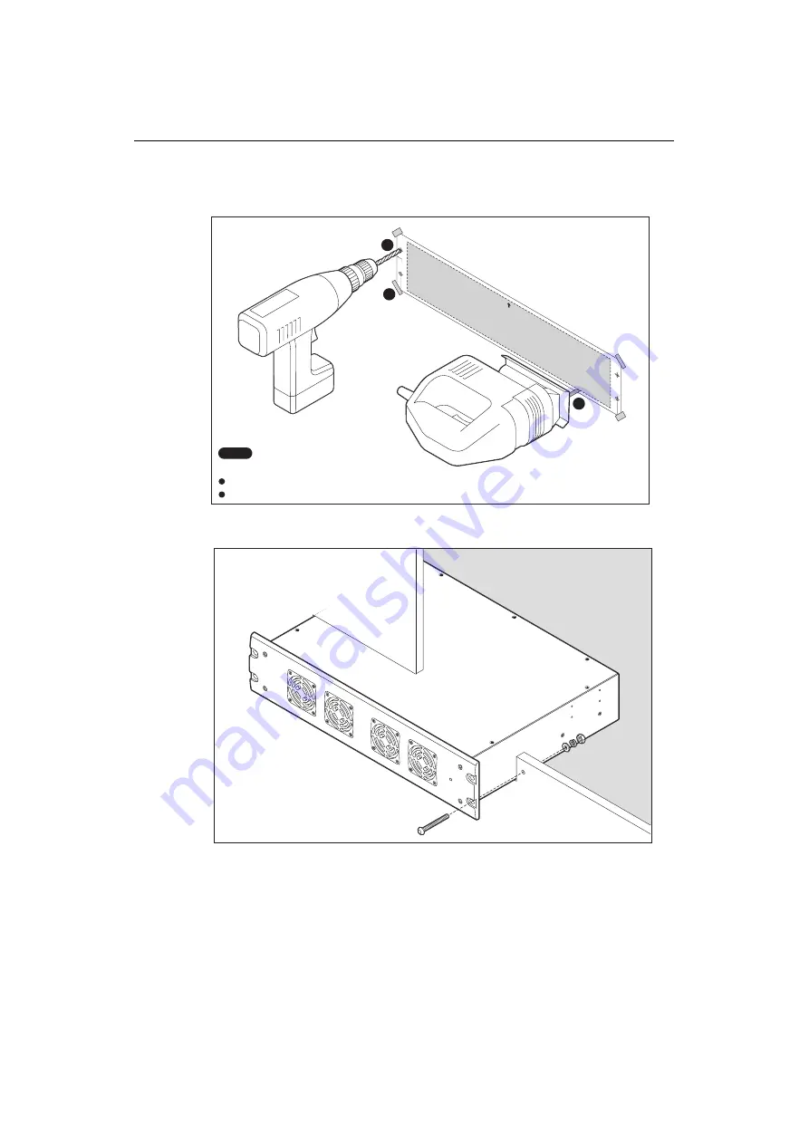
Power amplifier
Installation
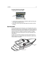
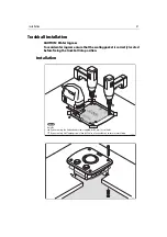
To install the power amplifier:
1. Tape the template into the required position.
2. Using the template drill a suitable size hole at each of the positions marked
A
for
the securing screws.
Fasc
ia
edge
D7319-1
UP
Rem
ove m
aterial
from sh
aded areas only
H6 Amplifier Unit
Mounting Template
Hole
A
Hole
A
Hole
A
Hole
A
1
2
3
D7418_1
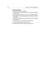
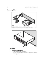
Check
Hole
A
If you are using th
e B
utton-Head screws supplied, drill 7 mm (
9
/
32
in) holes.
If you are using Self-Tapping screws, then drill holes of a suitable size to ensure secure fixing.
D7419_1
Summary of Contents for H6
Page 1: ...System Installation Manual Document number 87035_1 Date November 2004 D7579_1...
Page 6: ...4 Raymarine H6 System Istalation Manual...
Page 16: ...10 Raymarine H6 System Installation Manual...
Page 17: ...11 This page should be replaced with the A3 sheet System Schematic...
Page 18: ...12 Raymarine H6 Installation Manual...
Page 26: ...20 Raymarine H6 System Installation Manual...
Page 27: ...21 This page should be replaced with the A3 sheets Cables...
Page 28: ...22 Raymarine H6 Installation Manual...
Page 48: ...42 Raymarine H6 System Installation Manual...
Page 62: ...56 Raymarine H6 System Installation Manual...
Page 72: ...66 Raymarine H6 System Installation Manual...
Page 98: ...92 Raymarine H6 System Installation Manual No Check Confirmed...
Page 103: ...Raymarine H6 Connection diagrams Raymarine 2004...
Page 104: ...98 Raymarine H6 System Installation Manual...
Page 110: ...104 Raymarine H6 System Installation Manual...
Page 121: ...115 This page should be replaced with the A3 sheet VGA Connections...
Page 122: ...116 Raymarine H6 Installation Manual...
Page 123: ...Installation templates D7579_1...