


16
Raymarine H6 - System Installation Manual
Cable runs
CAUTION: Cable runs
Do not pull cables through a bulkhead or deckhead using a cord attached
to the connector. This could damage the connectors.
Cables and connectors used in Raymarine H6 form an integral part of the system. Some
cables are provided, others will have to be supplied.
Consider the following before installing the system cables:
• You need to attach power cables and scanner cables. Additional cables may be
required for long cable runs.
• If a cable needs to be longer, ensure that the cable being used is of the correct
quality and gauge. For example, longer power cable runs may require larger wire
gauges to minimize any voltage drop in a cable.
• All cables should be adequately secured, protected from physical damage and
exposure to heat. Avoid running cables through bilges or doorways, or close to
moving or hot objects.
• Acute cable bends must be avoided.
• Where a cable passes through an exposed bulkhead or deckhead, a watertight
feed-through should be used.
• Secure cables in place using tie-wraps or lacing twine. Coil any extra cable and tie
it out of the way.
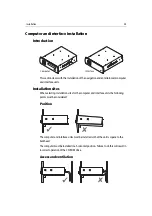
Computer, interface units and core components
When planning the installation of the computer, interface units and core components,
the following should be considered to ensure safe and reliable operation:
•
Position
- The computer and interface units should be mounted as a pair, i.e
navigation computer and interface unit, with the following:
• Maximum cable distance permitted between units - 0.8 m.
• Maximum cable distance permitted distance between navigation and
entertainment pairs - 20 m.
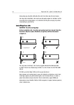
•
Remote control
- If the computer and interface units are to be located some
distance from the main helm, a remote control power switch may be required from
the navigation computer to the helm to facilitate ease of operation.
•
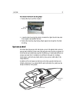
Convenience
- The mounting locations should be easily accessible to allow
operation of the front panel controls and CD-ROM drive.
•
Access
- There must be sufficient space behind the units to allow cable
connections to the unit connectors, avoiding tight bends in the cables.
Summary of Contents for H6
Page 1: ...System Installation Manual Document number 87035_1 Date November 2004 D7579_1...
Page 6: ...4 Raymarine H6 System Istalation Manual...
Page 16: ...10 Raymarine H6 System Installation Manual...
Page 17: ...11 This page should be replaced with the A3 sheet System Schematic...
Page 18: ...12 Raymarine H6 Installation Manual...
Page 26: ...20 Raymarine H6 System Installation Manual...
Page 27: ...21 This page should be replaced with the A3 sheets Cables...
Page 28: ...22 Raymarine H6 Installation Manual...
Page 48: ...42 Raymarine H6 System Installation Manual...
Page 62: ...56 Raymarine H6 System Installation Manual...
Page 72: ...66 Raymarine H6 System Installation Manual...
Page 98: ...92 Raymarine H6 System Installation Manual No Check Confirmed...
Page 103: ...Raymarine H6 Connection diagrams Raymarine 2004...
Page 104: ...98 Raymarine H6 System Installation Manual...
Page 110: ...104 Raymarine H6 System Installation Manual...
Page 121: ...115 This page should be replaced with the A3 sheet VGA Connections...
Page 122: ...116 Raymarine H6 Installation Manual...
Page 123: ...Installation templates D7579_1...