


14
Raymarine H6 - System Installation Manual
Safety of operation
An important part of planning the installation is ensuring the safe operation of the
system. Consider the following when planning the installation:
Trackball
The trackball(s) should be positioned so that the user’s wrist is supported during use.
This will avoid repetitive strain injury (RSI) to the user. The trackball(s) also need to be
adjacent to the display units.
Lifeline receiver
The Lifeline receiver should be installed in a horizontal position, adjacent to the main
helm trackball and displays for ease of operation.
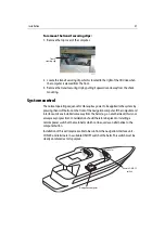
Audio-visual control unit
The audio-visual control unit must be installed in the horizontal plane, adjacent to the
main entertainments screen, with direct line of sight from seating to the unit to ensure
that the remote control functions correctly.
Pathfinder radar unit
The Pathfinder radar unit should be installed at the main helm adjacent to the H6
displays. Alarms created in H6 can only be cancelled using the Pathfinder unit.
Autopilot head
An autopilot head should be installed at each helm adjacent to the H6 displays. Safety
procedures require that the autopilot be controlled from the autopilot head not H6.
Off-vessel communications
There are several ways in which off-vessel communications can be established for H6.
This must be discussed in detail with the customer before installation. Factors which
affect what equipment will be required are:
• What type of boat is H6 being installed in.
• What is its main area of operation.
Having ascertained this information, a decision needs to be made as to which method
of connection will be most suitable for the type of operation; this can be achieved via:
• General Packet Radio Service (GPRS).
This is an ‘always on’ higher capacity connection providing internet and packet
based data services.
Summary of Contents for H6
Page 1: ...System Installation Manual Document number 87035_1 Date November 2004 D7579_1...
Page 6: ...4 Raymarine H6 System Istalation Manual...
Page 16: ...10 Raymarine H6 System Installation Manual...
Page 17: ...11 This page should be replaced with the A3 sheet System Schematic...
Page 18: ...12 Raymarine H6 Installation Manual...
Page 26: ...20 Raymarine H6 System Installation Manual...
Page 27: ...21 This page should be replaced with the A3 sheets Cables...
Page 28: ...22 Raymarine H6 Installation Manual...
Page 48: ...42 Raymarine H6 System Installation Manual...
Page 62: ...56 Raymarine H6 System Installation Manual...
Page 72: ...66 Raymarine H6 System Installation Manual...
Page 98: ...92 Raymarine H6 System Installation Manual No Check Confirmed...
Page 103: ...Raymarine H6 Connection diagrams Raymarine 2004...
Page 104: ...98 Raymarine H6 System Installation Manual...
Page 110: ...104 Raymarine H6 System Installation Manual...
Page 121: ...115 This page should be replaced with the A3 sheet VGA Connections...
Page 122: ...116 Raymarine H6 Installation Manual...
Page 123: ...Installation templates D7579_1...