background image

On the 

 SF 

screen, confirm that the number shown under 

ERASE

WAYPOMT 

is correct. Also verify that the 

 Protection feature for

the selected 

 is OFF. Press the 


E

RA

SE 


The

 will be erased.

WARNING !

Make sure that the 

 to be erased is NOT selected as your

current destination. Only waypoints protected “manually” cannot

be accidentally erased.

C. Copying Waypoints

Waypoints can easily be transferred from one memory location to another

using the COPY feature. To Copy waypoints: Press 


 on the

 List. On the Waypoint- SF menu press 


 When 

the 


screen appears, press 


Then type the 

 # (from) and 

 Then press the 

# (to) and press 

 again.

Example: 


 1, 5, 

.

Wpt 

 is now copied into wpt 

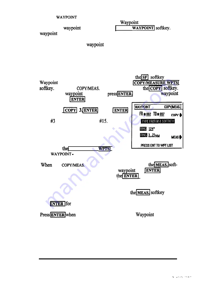
D. Measuring between Waypoints

You can easily measure the bearing and range

between any two waypoints stored in memory
by pressing 


COPY

/

MEASURE 

 soflkey

on the 

   SF screen.

 the 

 WAYPOINTS 

screen appears, press 

key. Then type the number of the “FROM” 

 and 

 followed

by the number of the “TO” waypoint. Press 

 key.

T h e   c a l c u l a t e d

bearing and range will then be displayed.

If you want to measure additional points, press 


 again.

The Fr and To digits will clear and you may re-enter a new pair of numbers.
Press

 the new Bearing/Range calculation.

 you are finished to return to the 

 List.

OPERATION 3-26


Summary of Contents for GPS navigation

Page 1: ...Distributed by Any reference to Raytheon or RTN in this manual should be interpreted as Raymarine The names Raytheon and RTN are owned by the Raytheon Company...

Page 2: ...i NAV398GPS IL RAI l GPSlLORAN OPERATION MANUAL...

Page 3: ...rical Connections 2 4 2 3 1 Power Input 2 5 2 3 2 Sensor Connections 2 5 2 3 3 Interface to External Navaids 2 6 2 3 4 Ground Connection 2 7 SECTION 3 OPERATION 3 1 G e n e r a l 3 2 The Keyboard 3 3...

Page 4: ...Ds 3 6 4 3 Entry by Bearing Distance 3 6 5 Waypoint List Operations 3 24 3 6 5 1 Selecting Waypoints 3 25 3 6 5 2 Editing Waypoints 3 25 3 6 5 3 SF Operations 3 25 3 7 Setting Alarms 3 27 3 7 1 Arriva...

Page 5: ...108 8 Channel GPS sensor or with both sensors together One key press gives you quick access to either navigation system The NAV unit includes storage for up to 500 waypoints and 10 route plans in the...

Page 6: ...le free and efficient operation of your new unit Section 3 covers the Operations of the NAV 398 and is intended to get you thoroughly familiar with the unit s controls and display formats The NAV 398...

Page 7: ...o the contents It is also good practice to save the carton and interior packing material until the unit has been installed on the vessel The original packing material should be used in the unlikely ev...

Page 8: ...gh the NAV 398 is designed to meet the toughest USCG waterproofing specifications common sense dictates that it should be mounted whenever possible so that it is not exposed to the direct effects of s...

Page 9: ...to the yoke and secure in the desired viewing position by tightening the yoke knobs IN THE YOKE BRACKET 4 HOLES 25 I 8 07 2 2 3 Flush Mounting The display can also be flush mounted in a console using...

Page 10: ...necessary to notch out some clearance in the cutout to pass the trim ring hardware through the panel 7 Complete the installation of the DC power cable data output and sensor wiring into the console as...

Page 11: ...ices FUSE RED BROWN DATA IN DATA OUT DATA OUT 12VDC WDC DATA IN Power Cable Wiring Diagram Although the NAV unit s power consumption is typically less than 5 watts if the power leads need to be extend...

Page 12: ...e connections are used for either NMEA or SeaTalk data The wires are marked and colored as follows YELLOW DATA GREEN DATA The NAV 398 may supply NMEA 0183 data for up to three external equipments Nava...

Page 13: ...L and RTE sentences 2 3 4 Ground Connection One important need in any installation is to obtain the cleanest noise free signals possible for measuring and calculating your position Part of this requir...

Page 14: ...714 w 118 35 236 3 N 34O14 714 b l w 118 35 236 l 0 POS 2 N 34Ol4 714 w 118 35 236 I123 m 093 m DTG Sffi 11 7nm 10 9kt NAV 1 I N 35 452 w115v5 223 MAIN DISPLAY MODES NAV 398 INSTALLATION 2 8 _ _ _ _ _...

Page 15: ...ill in using this full featured NAVigator where it counts afloat Thank you for selecting one of Raytheon s fine NAVigation products Great care and effort has been put into providing you with a useful...

Page 16: ...ates ContrastILite menu Accepts data for entry Reverts to Main menu or POS display resets numeric values to 0 silences audio beeper Selects Position displays selects digit 1 Selects NAVigation display...

Page 17: ...Contrast Setting When the BackLight menu appears use thelwpT 4 and T keys to vary the contrast level of the LCD for best viewing The level ranges from 0 to 15 The eikey increases the contrast level l...

Page 18: ...r a loran or GPS depending on the type of sensor that is connected or both if a sensor for each system is attached Normally if only one sensor is used the unit detects the type of sensor and automatic...

Page 19: ...gitude position once they have been powered up at the very first power up following installation or after a Master Reset the position finding process may take up to 30 minutes or more This startup tim...

Page 20: ...Globe figure on the previous page for verifying that the coordinate to be entered is truly your latitude Check to see that the direction symbol N is correctly indicated to the left of your latitude e...

Page 21: ...acking of signals for the I SIGNALSTATUS LORAN 1 sensor in use EST In normal tracking operation for loran the flA GRI chain and secondary signals received are indicated in the status box The most impo...

Page 22: ...ns always show your vessel s present position coordinates in the large 7 seg ment readouts of either Lat Lon or loran TDs Each POS screen combines different navigation information with the position co...

Page 23: ...ed as the destination waypoint w 118 35 236 The CD1 is made up of a boat like symbol and a scale depicting your vessel s deviation from an intended track line to the destination On this CD1 screen the...

Page 24: ...I and the desired TD lines must be intitially entered in the GPS Setup mode before this conversion page can work properly However having entered the required initial data the conversion program can op...

Page 25: ...IM s il key down for the beep The POS custom page will appear Initially all the POS screens will be ON This is indicated by the black dot after the page name To turn a page OFF press the correspondin...

Page 26: ...run units and steering direction indicator plus the Time to go TTG readouts The NAV 4 screen combines the Course made good CMG and velocity to destination VTD readouts with the COG and SPD readouts i...

Page 27: ...and DTG readouts will be blank WPT NO DEST appears in the message window and the destination target symbol is not displayed 3 5 5 Plot Display Mode One of the most useful modes is the Tracking Plotte...

Page 28: ...N m PRESS CLEAR TO EWT You can record and save a single important vessel track of your vessel s trip to keep in memory so when you return home you may retrace the same route Recording a track is easil...

Page 29: ...y to return to the previous display mode to back out of the menus Erasing a Track Line Since only one track line can be stored to memory at any time in the NAV unit it s a good idea to erase the old t...

Page 30: ...Destination Press the wi key Enter the waypoint using three digits and then press ENTET 1 3 5 7 1 Saving Events You can save your present position for future use as a waypoint when you are in any of...

Page 31: ...cters on the screen In this way the operator can use the matching systems to return to Event locations more accurately It s a very good idea to write the Event numbers and location descriptions onto y...

Page 32: ...start a new track from where you are than to return to the old track to waypoint To start a new track just press thelwlkey followed by the numbers of the same waypoint Then press theF key and the NAV...

Page 33: ...formation the waypoint memory location number has to be entered first This is necessary so the NAV unit can place or retrieve the information from the correct memory Since there are so many waypoint m...

Page 34: ...t waypoint coordinate data Pressing one of the softkeys will help you make that selection ENTERNEWWPT Pressing this so key selects next available empty waypoint memory IENTERWPTNO _ 1 If you want to s...

Page 35: ...name can consist of up to 8 char acters Each character selected at the EIRST I NAM WAYPOINT 8002 1 nom will be used to designate that way point on the Plot display Softkeys provide a quick means to s...

Page 36: ...you can select the type of coordinate data to enter 1 STORE WAYPOINT TYPE 1 If you wish to enter the waypoint coordinates in Latitude Longitude press thelm soft WFTJmo2 STORE WPT Bv lAT LONG key To e...

Page 37: ...ue waypoint entries press1 ENTER WPT NO 1 If you want to recheck the new entry press1 GOTO WAYPOINT LISA key Press 1 if you are finished This will return you back to the previous display mode 3 6 4 2...

Page 38: ...45 Now the DISTANCE RNG can be entered using three digits up to 99 9 If the range is less than 10 0 miles type a 0 first followed by the remaining two digits Press 1 when the DISTANCE value is displa...

Page 39: ...display changes to WAYPOINT SF 3 6 5 3 SF Operations If you press the m key on the Waypoint List display you can perform some additional operations with the stored waypoint data including the followi...

Page 40: ...ess theI softkey Then type the waypoint from and press 1 Then press the waypoint to and press ENTERI again Example I 34 1 1 5 ENTEd Wpt 3 is now copied into wpt 15 D Measuring between Waypoints You ca...

Page 41: ...alarm K Press thel key The SET NAV ALARMS screen appears This is the alarm set up screen Press theI softkey Then enter the distance value for the desired arrival alarm zone with the numeric keys Press...

Page 42: ...to press thd key as you drop anchor to store your present position as a waypoint Make a mental note of the EVENT memory number The number appears for approximately 3 seconds on the dispIay and certain...

Page 43: ...cters will appear on screen in the alarm warning area Presdm to silence the audio beeper The values set for the alarms will remain in memory until changed by the operator As mentioned earlier you can...

Page 44: ...MOB mode is cancelled If you will need to retain the location for some reason mark the location with themjkey after the mode is cancelled 3 9 Route Plans The NAV 398 allows you to create up to 10 rou...

Page 45: ...waypoint 004 FROM 6l JTO g The screen will show the From waypoint as 004 and add the TO entry line for the next waypoint number entry Type the digits of the next point in the route plan If you make a...

Page 46: ...rns the route sequence mode to OFF Press th EQUENCE MODElsoftkey to high light the desired sequencing mode AUTO SEQUENCING mode automatically steps from one waypoint to the next when the arrival perpe...

Page 47: ...or press ml OJm the route will be turned OFF 3 9 3 Editing Route Plans The EDIT ROUTE mode is used to INSERT or DELETE waypoints in a route plan or to ERASE a route plan in its entirety Press the ROU...

Page 48: ...not from waypoint memory B JWhen you are finished press theI key to end the editing session and return to the Display mode If you press the CLEAR key here which is normally done on other menus you wil...

Page 49: ...ilable when the key is actuated The Svstem setuos control Data Inputs Outputs Units of Measure and Language The NAV setuns change the parameters for calculating and displaying the navigation data Item...

Page 50: ...e figure below STATUS MENUS LORAN C STATUS mou SIGNK ON STATUS MENU IF LOWN IS SEIJXTEDASNAVTVPE I BA ENTER S2 PRESS ENTER TO GElURN I TOGGLES moht r4x On this display the characters show the selected...

Page 51: ...nal is directly related to the received strength of the signal SNR If the signals are very weak it usually takes much longer to Lock on and track the signals and display your position The table below...

Page 52: ...erent GRI from the internal GRI list or the msl sz lsoftkey to change the secondaries stations only Selecting GRIs Manually Thdm softkey toggles through the list in numerical order The GRI names appea...

Page 53: ...mode and theI key is pressed andISIGNAL STATUS is selected from the Menu Directory the GPS Status screen will appear and show the GPS satellite signals I y j 0141MT SF PRESS CLEARTO EXIT I The Satelli...

Page 54: ...ce 3 10 2 5 Initializing GPS Sensors The following paragraphs describes the series of initialization inputs to be checked when your NAV unit is to be operated with the RAYSTAR 100 or RAYSTAR 108 GPS S...

Page 55: ...evel in METERS 3 28 feet 1 meter or in FEET Enter the numeric value of you antennas height above the water Then press j When thdm softkey appears on the screen press the softkey only if you want to ch...

Page 56: ...d L L position will appear in the entry window If the GRI is correct then it is only necessary to designate the TD numbers Press Sl softkey and type two digits of first TD Press 1 When the softkey arr...

Page 57: ...ftkey for OOO readouts When the lmjsoftkey is pressed the SF2 menu will appear On this menu you can set the Time Date readouts on the GPS Signal Status page to show the UTC Time Date when the ml softk...

Page 58: ...YSTEM UNITS appears On this screen the units for distance and speed language and CD1 scaling may be selected Themlkey appears again on the UNITS menu and this time toggles the selection of NM KTS SM M...

Page 59: ...irectional data for mat used for communication between Autohelm Instruments and Raytheon ma rine products OUTPUT ROUTE DATA 0 1 0 0 m SEATALK Press the NMEA DATA OUTjsoftkey to highlight your choice M...

Page 60: ...If everythings connected correctly on the SYSTEM STATUS DATA menu press the MEMORY DATA IN sofkey The screen will show the message LOADING WP DATA IN and DOWNLOADING will blink on the screen during th...

Page 61: ...r manual Magnetic bearings True North mode When the unit is shipped from the factory the readouts for Course and Bearing are displayed in Magnetic North To display True North data it is necessary to d...

Page 62: ...n will be determined by the sensor that is currently selected for use To apply corrections to the loran L L you will need to be sure the unit is in the loran mode Conversely be in GPS mode to do GPS c...

Page 63: ...ng the softkey steps the selections from AUTO to MANUal to OFF etc Manual TD Corrections Although adding TD correction values to correct your Lat Lon position is not a common practice there are times...

Page 64: ...he two Latitudes and the two Longitudes from each other to determine the appropriate correction to be entered into the NAV unit Example N42 42 23 Loran W071 24 54 Loran N42 42 08 Chart WO7124 50 Chart...

Page 65: ...menus that are particular to GPS operation The COURSE BEARINGS menu of the NAV SETUPS menu happens to have the same operations for both Loran and GPS The operations for selecting magnetic bearings we...

Page 66: ...the POSITION CORR GPSl menu is dis played the screen displays the current Geodetic datumused by the GPS sensor To move through the datum list and select a different datum press GEODETICSYSTEM down to...

Page 67: ...LD EGYPTIAN OLD HAWAIIAN PICO DE LAS NIEVES PROV SO AMERICAN 1956 PROV SOUTH CHILEAN PUERTO RICO QOWOQ RT90 SANTA BRAZ SOUTH AMERICAN 1969 SOUTHWEST BASE 47 TIMBALAI 1984 Ethiopia and Sudan Botswana A...

Page 68: ...become highlighted by a reverse block Type the numbers of the Lat correction value and press 1 The N S prompt appears Use the softkey if necessary to set the desired direction Then press l Now type t...

Page 69: ...e receiver is operating in the automatic mode The fre quency of the beacon is dis played DGP6 BEACON STATUS A FREGUENCY 206 KHZ AUTO B A U D RATE c 100 mull 0 RSSI 56 MANU mmsammm Each beacon operates...

Page 70: ...eacons are more numerous towards 1996 it is possible that more than one strong beacon signal may be picked up in some areas Manual tuning assures that only the desired beacon will be received 3 10 5 3...

Page 71: ...ons to the ship s DC power and RF ground system are clean and tight A light coating of a high insulation silicon grease such as Dow Corning DC 4 on connector pins can protect the plug contacts from co...

Page 72: ...aler or by the Raytheon Factory Service Center 4 4 Master Reset The NAV 398 unit is a microprocessor based equipment and like most computers it runs smoothly and efficiently in normal use However unde...

Page 73: ...ace with 2 Amp fuse Not Receiving SNR readings 0 Lat Lon reading does not change Check Sensor connections Check Signal Status Check Initial settings Check Est L L entry Check GRI is correct Check Est...

Page 74: ...ccepts NMEA 0 183 GLL GTD VTG RMA Data Input Port NMEA 0183 WPL RTE STN LCD Dot Matrix 240 x 240dots FL panel Lithium Battery 3 5 years lo 16 VDC Less than 6 watts N or S 6 digits OOl min resolution E...

Page 75: ...Italian German ERR for Low SNR Blink Cycle selection no L L solution On screen indicator and audible alert for Arrival XTE or Anchor Watch alarms 4 6 3 Physical and Environmental Operating Temperatur...

Reviews: