background image

66

DSM300 Operation with PLUS Series Displays

You adjust gain for each transducer frequency independently. Press the GAIN 
ADJUST soft key to highlight the frequency for which you are making adjustments. 
You may change settings for one frequency while displaying the other.

To adjust a parameter:

1. Press the 

GAIN

 key or rotate the 

GAIN

 knob on radar CRT units. The gain 

sliders are displayed. The slider last used is highlighted (displayed in inverse 
video) to show that it is selected.

2. If necessary, press the GAIN ADJUST soft key to select the desired frequency 

for adjustment.

3. If necessary, press the desired soft key to highlight (select) the desired slider.

Press it again, if necessary, to toggle between AUTO and MANUAL modes.

4. In manual mode, use the trackpad to move the selected slider up or down. You 

can press and hold the trackpad to move the slider quickly rather than in sin-
gle steps.
As you move the slider, the value displayed in the slider is updated. The new 
setting takes immediate effect.

Note:  

Because the changes to the settings take effect immediately, you cannot revert to 

the previous settings by pressing 

CLEAR

5. When you have set all the controls to the levels you desire, press 

ENTER

 or 

CLEAR

 to return to the default display.

Gain

The GAIN, or sensitivity, of the display adjusts background noise by varying echo 
strength for display. The value of the gain control determines the strength above 
which echoes are displayed. If the gain is low only the strongest echoes are 
displayed. As the gain is increased, weaker echoes (from air bubbles, for example) 
are also displayed. 

Pressing the GAIN soft key cycles the sounder from manual through three levels of 
automatic gain adjustment. 

Manual gain should be set high enough to see fish and bottom detail but without 
too much background noise. Generally, a high gain is used in deep and/or clear 
water; a low gain in shallow and/or murky water.

The automatic gain modes finds the ideal sensitivity level for you, based on depth 
and water conditions. Automatic gain modes take advantage the hardware’s 
advanced DSP technology. As a result, the sounder typically achieves a sharper 
image in any of the automatic gain modes than is possible in manual mode.

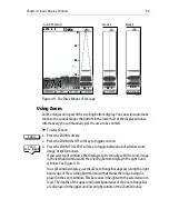
GAIN

ADJUST

200 50

MULTI

GAIN

GAIN

ADJUST

200 50

GAIN

MANUAL

GAIN

80%

Summary of Contents for DSM300

Page 1: ...DSM300 Digital Sounder Module Operation with hsb2 PLUS Series Displays Document number 81249 1 Date November 2004...

Page 2: ...Autoseastate Autotrim Bidata Marine Intelligence Maxiview On Board Raychart Raynav Raypilot Raystar ST40 ST60 Seaclutter Smart Route Tridata and Waypoint Navigation are trademarks of Raymarine Limite...

Page 3: ...electing Repeater Mode 15 2 5 Sonar Mode Display 16 2 6 Operating Modes 18 Horizontal Half Screen Window Options 18 Vertical Half Screen Window Options 18 Sonar Options 19 Sounder Functions 20 2 7 Sim...

Page 4: ...n Serial Numbers 38 Chapter 4 Basic Display Controls 39 4 1 Introduction 39 Simulator 39 4 2 Setting Color and Brightness 39 Lighting and Contrast Monochrome Displays 39 Brightness and Color Settings...

Page 5: ...5 Adjusting Display Gain Sensitivity 65 Color Gain 67 5 3 Using VRM 70 5 4 Waypoints 71 Placing a Waypoint 72 5 5 MOB 73 Appendix A List of Abbreviations 75 Index 79...

Page 6: ...6 DSM300 Operation with PLUS Series Displays...

Page 7: ...st be installed and operated in accordance with the instructionscontainedinthismanual Failuretodosocanresultinpersonalinjury and or navigational inaccuracies In particular CAUTION High Voltage The DSM...

Page 8: ...R The soft key functions menu names and options are shown in normal capitals for example SCREEN Operating procedures which may consist of a single key press or a sequence of numberedsteps areindicated...

Page 9: ...es that fish and bottom structure are presented in superb detail and optimal colorallocation The DSM300 digital bandwidth adaptation adjusts the receiver band width dynamically from very wide to very...

Page 10: ...ditional data Position data requires GPS 1 3 How to Use this Handbook This handbook describes how to operate a DSM300 with your hsb2 PLUS Pathfinder Series display unit Instructions for operating the...

Page 11: ...Overview 11 Figure 1 2 DSM300 in an Integrated System MENU CH OK 16 9 HI LO SCAN WATCH SQ WX D7463 1 Power Supply DSM300 Transducer GPS VHF Radio NMEA SeaTalk RS 232 Interface Box Radome PLUS Display...

Page 12: ...12 DSM300 Operation with PLUS Series Displays...

Page 13: ...ettingchangetowhen theDSM300placesitinmemory Ifyoupowerdownthesounderlessthanoneminuteafter making a change thesetting is lost 2 2 Powering on the Sounder Module There is no power switch on the DSM300...

Page 14: ...the DISPLAY pop up then press again to cycle through the modes available shown in Figure 2 1 Figure 2 1 Using the DISPLAY Key The selected mode isshown by an icon with a black monochromedisplay or re...

Page 15: ...onar data You must tell the display it is to be a repeater for the DSM300 and not a master unit on its own IfyourDSM300isrepeatingitssonardataoveraPLUSSeriesradarorchartplotter display the proper sett...

Page 16: ...The sonar screen includes a status bar that displays transducer frequency and indicates which auto settings are enabled Gain Color Gain Range Zoom and Frequency and alarm status fish and shallow deep...

Page 17: ...ZFH 50kHz 0 SD 60 20 40 18 22 38 35 36 33 32 36 37 42 ft Gain Color gain Range Cursor controlled by trackpad Auto Mode Indicators Water surface Frequency Target Depth ID On Alarm enabled Frequency Pow...

Page 18: ...plits the sounder vertically The left hand window displays data boxes there are three different sets of data A B and C that you can select for display The following information is available only in So...

Page 19: ...ottom Itprovidesa bottom up view the bottom is used as the reference its image is flattened and depths are displayed here Bottom lock mode is used primarily to filter out the bottom structure and dis...

Page 20: ...dataisdisplayedinahalf screen window Sounder Functions The DSM300 includes the following functions Automatic or manual selection of scroll speed for bottom graph display Automatic or manual selection...

Page 21: ...le you can still operate in Simulator mode by connecting the DSM to the display device Then connect the DSM300 and the display unit to a 10 7 32VDC power supply attaching the red wire from the power l...

Page 22: ...layed 3 Use the trackpad to move the selection bar over the option SONAR SIMULATOR The simulator soft keys are displayed 4 Press the ON soft key to switch on the sonar simulator 5 Press ENTER twice to...

Page 23: ...Note All settings describedinthis chapterare retained when theunitis powered off However thereis aone minutedelayfromthetimeyoumakethesettingchangetowhen theDSM300placesitinmemory Ifyoupowerdownthesou...

Page 24: ...Someparametersarecontrolledbya sliderthatisdisplayedabovetwoof the soft keys For some parameters a soft key provides access to a sub menu of further options 4 Press the soft key corresponding to the d...

Page 25: ...DEPTH COG SOG TIME DATE WIND WAYPOINT CROSS TRACK ERROR HEADING LOG TRIP PILOT VMG TEMPERATURE TIDE SET DRIFT OFF LAT LONG or TDs OFF or ON OFF or ON OFF or ON OFF or ON OFF or ON OFF or ON OFF APPAR...

Page 26: ...OFF or ON OFF NMEA OUT SET UP APB BWC BWR DBT DPT MTW RMB RSD RTE TTM VHW VLW WPL GGA GLL RMA RMC VTG ZDA OFF or ON OFF or ON OFF or ON OFF or ON OFF or ON OFF or ON OFF or ON OFF or ON OFF or ON OFF...

Page 27: ...of the graphics can still be seen The ones you select here can be turned on and off as a group during normal operation and you can also move them around the screen individually using the context sensi...

Page 28: ...range and bearing Alternatively you can show both types of readout in separate boxes or turn the cursor data box off You can also turn the cursor readout box es on and off during normal operation via...

Page 29: ...the autopilot changes they are displayed in a pop up box Thebox is removedfrom thedisplayaftertwo seconds When Autopilot Pop set to OFF the pop up box is disabled Menu Timeout Period With no timeout s...

Page 30: ...tnoNMEAvariationisavail able then variation is taken from SeaTalk If heading is taken from SeaTalk but no SeaTalk variation is available then variation is taken from NMEA 3 Acalculatedvariationvalue u...

Page 31: ...ur sounder Forexample if the DPT depth sentence is setON butthe sounder stransducer is designed to sense temperature and speed only the depth value will be transmitted as zero If you also have an ST60...

Page 32: ...art window Whentheappropriateoptionsareswitchedon eachdisplayshowsitsowncursor plus the cursor of the other display with appropriate cursor text RDR or CHRT to indicateitsorigin Thismeansthatyoucouldm...

Page 33: ...gmotion of theboat givinga clearerindicationofthe boat scourseand speed The filter does not affect the calculation of the GPS position The velocity vectors calculated from the GPS Signal give an insta...

Page 34: ...ot change if you change the range although the range rings are adjusted see radar documentation Both provides simulated data and radar picture When the simulator is switched on a SIMULATOR data box is...

Page 35: ...play Sonar HSB Mode Note ThisparameteronlypertainswhenthedisplaytowhichyouareoutputtingDSM300 imagedata is a PLUSSeries fishfinder If yourdisplay is aPLUSSeries radaror chartplotter display the REPEAT...

Page 36: ...ustsetthefishfinderdisplaytoREPEATERsothatthereisnoconflictonthehsb2 network the DSM300 is always designated as a master You would only select MASTER when you want to control the PLUS Series fishfinde...

Page 37: ...sthe numberof data sample columnsthatappearonthe screen at one time The options are SMALL which displays 240 columns of data or LARGE which shows 480 columns Information displayed in a single column u...

Page 38: ...ion of STC Version Serial Numbers TheareaatthebottomoftheSonarSetupscreengivesversioninformationforthe system This area is informational only it is not editable DISPLAY SW VERSION displays the softwar...

Page 39: ...rating display controls in Sonar Mode without data from the transducer Section 2 7 describes how to switch the display to simulator mode TheDSM300mustbeconnectedtoanhsb2 PLUSSeries CSeriesorESeriesdis...

Page 40: ...nless you set the control very low or very high in this case the contrast will be restored as follows Contrast set 30 restored to 30 Contrast set 70 restored to 70 Brightness and Color Settings Color...

Page 41: ...thedisplayison PressMULTI and thenuse the trackpad to increasebrightness You canalsopress and hold MULTI for one second to set the brightness to 100 Selecting the Background Color Fivecolorsareavailab...

Page 42: ...A Scope To change the color threshold 1 Press the MULTI key to display the soft key controls 2 Press the COLOR SETTINGS soft key 3 Press the COLOR THRESH soft key The color threshold softkeysaredispl...

Page 43: ...escribes how to select the mode of operation and switch half screen windows on off The controls are summarized in the laminated Quick Reference card that accompanies this handbook Selecting the Displa...

Page 44: ...izontal Half Screen Window Options Using horizontal half screens the main operating mode is displayed in the upper window you choose what is displayed in the lower window The following information if...

Page 45: ...screen Sonar mode press theDISPLAY key The following soft keys are displayed with an image of each available window 2 Set SPLIT to HOR To select a different window press either SELECT WIN DOWS soft k...

Page 46: ...20 20 10 10 nm nm WPT BRG WPT RNG TTG 1 45nm 23 1nm 01h 13m STEER STARBOARD WAYPOINT 001 351 T SELECT WINDOWS WINDOWS OFF ON SPLIT HOR VER 0 20 40 20 40 ft ft 60 60 60 60 CDI Window BDI Window D6166...

Page 47: ...each window provides several large format data boxes for specific information as follows Data Window A provides surface temperature with a 30 minute tempera ture graph speed through water and depth Da...

Page 48: ...OWS OFF ON SPLIT HOR VER D6191 1 DISPLAY TO SELECT FULL SCREEN OPTION SOFTKEYS TO SELECT WINDOW OPTION CHART SONAR LOG RADAR ZOOM FREQUENCY BTM LOCK A SCOPE AUTO GC F 50kHz 0 DEPTH ft SPEED kts 20 1 1...

Page 49: ...toggle operating control between the sounder and the chart window using the CHRT SNR soft keys To change the active window when you are displaying the sonar chart horizontal split window press the CH...

Page 50: ...informationusing anappropriatescrollspeedandrange However controlsareprovidedsoyoucan adjust scroll speed and range You can also select the transducer frequency and select certain data for display Thi...

Page 51: ...is useful when you are looking for fish if you select a slower speed the information remains on the display for longer Figure 4 7 Effect of the Scroll Speed The DSM300 defaults to manual scroll adjus...

Page 52: ...NTER to return to the Menu soft keys then ENTER again to return to the default display Selecting the Power Setting The POWER softkey provides adjustment of the transducersignal When AUTO is selected d...

Page 53: ...bottom and A Scope displays You can also set the shift value to move the image window up or down within the current range The following range shift values are available Table 4 2 Range and Shift Valu...

Page 54: ...w is shifted up by the selected amount Pressing the SHIFT keys sets the range to MANUAL 5 Press ENTER to return to the default display Selecting the Frequency TheDSM300usesdualfrequencysonar 50 kHzand...

Page 55: ...soft key The frequency selection soft keys are dis played 2 Press the appropriate soft key 50 KHZ 200 KHZ or SPLIT The scrolling bot tom is displayed in the selected frequency If you choose split the...

Page 56: ...ttom See Target Depth ID on page 35 To display the Bottom Lock image 1 Press the BTM LOCK soft key The Bottom Lock selection soft keys are dis played 2 Press the BTM LOCK OFF ON soft key to toggle the...

Page 57: ...he bottom lock image or CLEAR to cancel the operation Using A Scope The scrolling bottom display provides a historical record of sonar echoes Use the A Scope screen to show raw sonar data directly fro...

Page 58: ...with depth ii Mode 2 in which the image expands to take up the entire A Scope win dow providing greater resolution iii Mode3 inwhichonlythelefthandsideoftheimagedisplayedinMode2 expands to the entire...

Page 59: ...selectsplitwindows the display issplitvertically with the zoom image in the left hand window and the scrolling bottom display in the right hand window See Figure 4 10 In a split window display a verti...

Page 60: ...el is selected The greater the zoom the smaller the area you are viewing so the smaller the Zoom Range Bar 6 Press ENTER or CLEAR to select To turn off Zoom 1 Press the ZOOM soft key The Zoom soft key...

Page 61: ...g the line UP toward the surface moves the Zoom Window DOWN toward the bottom Moving the Zoom Position Line DOWN moves the Zoom Window UP Note If youwish tomove the window beyond whatis displayed youm...

Page 62: ...oth frequency windows Notes 1 TheverticalZoomRangeBarshowstherangebeingdisplayedinthezoom left side window 2 Thesizeofthiszoomrangeisdeterminedbythezoomfactor 2x 4xor6x 3 Thepositionofthezoomrangeonth...

Page 63: ...cations using the white line feature and adjusting gain sensitivity Viewing Data Windows Setting up and Using Alarms for fish shallow water and deep water Using a VRM to Determine Depth and Distance f...

Page 64: ...ths are displayed The color displaysalsoletyouselectthebackgroundcolorandremovethedisplaycolorsfor weaker echoes ThesounderprovidesaWhiteLinefeaturewhichhelpstodistinguishbetweenthe bottom and fish or...

Page 65: ...line feature on and off 1 Press the MULTI key knob The WHT LINE soft key is displayed 2 Press the WHT LINE soft key to toggle the white line feature ON or OFF Adjusting Display Gain Sensitivity The so...

Page 66: ...the settings takeeffectimmediately youcannotrevertto the previous settings bypressingCLEAR 5 When you have set all the controls to the levels you desire press ENTER or CLEAR to return to the default d...

Page 67: ...ee monochrome or seven color bands to correspond with each shade of gray color Thecolorbarontherighthandsideofthedisplay whensettoONintheSonarSet Up menu see Section 3 4 shows the colors being used wi...

Page 68: ...mance transducers You maywanttousetheshallowanddeepwateralarmswhenyouareanchored Setthelimits to justabove and below your anchordepth the sounder triggers an alarm if the anchor drags and the boat mov...

Page 69: ...hese alarms by pressing any key No other action is taken except to silence the alarm To set an alarm 1 Press the ALARMS key The alarms soft keys are displayed 2 Fortheshallowordeepalarms presstheSHALL...

Page 70: ...ow The VRM distance units correspond to the depth units assigned in the system set up parameters you have assigned for your display unit as follows The distance from boat continues to update as your b...

Page 71: ...ff or Move the cursor over the VRM until the textVRM appears then press CLEAR 5 4 Waypoints The MARKS key lets you to place up to 998 waypoints A waypoint is a position normally entered on a chart as...

Page 72: ...E WPT AT CURSOR or the PLACE WPT AT VESSEL soft key The waypoint is added to the waypoint list and tagged using the next available number Thewaypointsoftkeysaredisplayeduntilyoumovethecursorawayfromth...

Page 73: ...he Waypoint List and named with the next available number To return to the default soft key display press ENTER or CLEAR twice For fulldetailson working withwaypoints referto the handbook foryourdispl...

Page 74: ...laystheMOBdatabox showingthebearinganddistancefromyourboat to the MOB waypoint position and the elapsed time since the MOB was initi ated Figure 5 1 Sounds a 4 second alarm pattern every 30 seconds Se...

Page 75: ...ent Lamp CDI Course Deviation Indicator COG Course Over Ground CPA Closest Point of Approach DC Direct Current DSC Digital Selective Calling DSM Digital Sounder Module EBL Electronic Bearing Line EMC...

Page 76: ...Long Longitude Man Manual MARPA Mini Automatic Radar Plotting Aid MPH Miles per hour nm Nautical Mile NMEA National Marine Electronics Association RTE Route s seconds SHM Ships Heading Marker sm Stat...

Page 77: ...Appendix A List of Abbreviations 77 UTC Universal Time Constant VMG Velocity Made Good VRM Variable Range Marker WPT Waypoint XTE Cross Track Error...

Page 78: ...78 DSM300 Operation with PLUS Series Displays...

Page 79: ...r Gain 67 Gain 65 Range 53 Scroll Speed 51 STC 68 Cursor Readout 25 28 Reference 25 28 Cursor Data Box 50 Cursor Echo 26 32 D Data Box 25 27 50 COG 25 47 Cross Track Error 25 Date 25 Depth 25 47 Group...

Page 80: ...y 75 GPS SOG COG Filter 27 33 H Half Screen Windows 46 Horizontal 18 44 Vertical 18 47 Heading 31 74 Heading Data Box 25 Help 25 28 High Voltage 7 Horizontal Half Screen Windows 18 44 K Key Beep 25 29...

Page 81: ...ock 19 55 White Line 64 65 Zoom 19 59 Echoes 16 40 Signal Strength 64 Functions 20 HSB Mode 35 Mode 18 44 Full Screen 18 Set Up 23 34 Simulator 21 22 35 38 39 Switching Control Between Sounder and Dis...

Page 82: ...47 Database List 71 73 Placing 71 White Line 64 65 Wind Data Box 25 Window Options BDI 18 44 46 CDI 18 44 46 Chart 18 44 46 Depth Temp 18 44 46 Full Screen 18 44 Horizontal Half Screen 18 44 Nav Data...

Reviews: