background image

Chapter 10: System checks and troubleshooting

Chapter contents

10.1 Augmented Reality (AR) initial test on page 56

10.2 GNSS (GPS) check on page 56

10.3 Troubleshooting on page 58

Summary of Contents for AR200

Page 1: ...Installation instructions AR200 ...

Page 2: ...oduct overview 16 3 2 Required additional components 17 Compatible MFDs 17 Multifunction display software requirements 18 3 3 Software updates 18 Chapter 4 Parts supplied 19 4 1 Parts supplied 20 Chapter 5 Product dimensions 21 5 1 Product dimensions 22 Chapter 6 Location requirements 23 6 1 Selecting a location 24 Warnings and cautions 24 Location requirements 24 RF interference 25 Compass safe d...

Page 3: ...p 48 Fixed camera calibration 48 Pan and Tilt camera calibration 49 9 2 AR200 Calibration Linearization 51 Magnetic deviation 52 AR200 calibration settings 52 Continual monitoring and adaptation 53 Compass lock 54 Chapter 10 System checks and troubleshooting 55 10 1 Augmented Reality AR initial test 56 10 2 GNSS GPS check 56 10 3 Troubleshooting 58 LED Diagnostics 58 GNSS GPS troubleshooting 60 Au...

Page 4: ... specification 71 14 1 Technical specification 72 Power specification 72 Environmental specification 72 Conformance specification 72 GNSS GPS receiver specification 72 AHRS specification 73 Chapter 15 Spares and accessories 75 15 1 Accessories 76 15 2 SeaTalkng cables and accessories 76 Appendix A NMEA 2000 PGN support 83 ...

Page 5: ... hazardous flammable atmospheres Do NOT install in a hazardous flammable atmosphere such as in an engine room or near fuel tanks Warning Product grounding Before applying power to this product ensure it has been correctly grounded in accordance with the instructions provided Warning Positive ground systems Do not connect this unit to a system which has positive grounding Warning Switch off power s...

Page 6: ...by third parties Suppression ferrites Raymarine cables may be pre fitted or supplied with suppression ferrites These are important for correct EMC performance If ferrites are supplied separately to the cables i e not pre fitted you must fit the supplied ferrites using the supplied instructions If a ferrite has to be removed for any purpose e g installation or maintenance it must be replaced in the...

Page 7: ...Chapter 2 Document information Chapter contents 2 1 Product documentation on page 14 ...

Page 8: ...face may differ slightly from that shown in the illustrations in this document depending on product variant and date of manufacture All images are provided for illustration purposes only Operation instructions For detailed operation instructions for your product refer to the documentation that accompanies your display Applicable products This document is applicable to the following products Part n...

Page 9: ...Chapter 3 Product and system overview Chapter contents 3 1 AR200 product overview on page 16 3 2 Required additional components on page 17 3 3 Software updates on page 18 ...

Page 10: ...a live camera feed being displayed on your MFD This enhances your situational awareness by allowing you to quickly see the position of these data objects relative to your actual field of view in front of your vessel Note For more information about Augmented Reality and how it is used on your MFD refer to 81370 LightHouse 3 Advanced operation instructions The AR200 provides position heading pitch a...

Page 11: ... later Required components for Augmented Reality M Series cameras MFD Axiom Axiom Pro or Axiom XL M Series camera M100 M200 and M300 Series M100 M200 Series cameras require LightHouse software version 3 9 or later M300 Series cameras require LightHouse software version 3 10 71 or later Important Cameras utilizing ClearCruise Augmented Reality are subject to an unstable image on rough waters Recomm...

Page 12: ...updates to improve product performance and add new features The software on many products can be updated using a connected and compatible multifunction display MFD Important To prevent potential software related issues with your product always follow the relevant update instructions carefully and in the sequence provided If in doubt as to the correct procedure for updating your product software re...

Page 13: ...Chapter 4 Parts supplied Chapter contents 4 1 Parts supplied on page 20 ...

Page 14: ...Stainless steel 5 Mounting tray Bottom 6 4 x small surface mount fixings Pan head pozi DIN7981 ST 2 9x13 C Z A4 Stainless steel 7 Bulkhead Wall bracket 8 Large sealing ring 9 Documentation 10 6 m 19 69 ft SeaTalkng White cable Unpack your product carefully to prevent damage or loss of parts check the box contents against the list above Retain the packaging and documentation for future reference ...

Page 15: ...Chapter 5 Product dimensions Chapter contents 5 1 Product dimensions on page 22 ...

Page 16: ...5 1 Product dimensions ...

Page 17: ...Chapter 6 Location requirements Chapter contents 6 1 Selecting a location on page 24 ...

Page 18: ...ning Potential ignition source This product is NOT approved for use in hazardous flammable atmospheres Do NOT install in a hazardous flammable atmosphere such as in an engine room or near fuel tanks Location requirements The installation location must take into account the following requirements The unit should be installed above decks Choose a location that provides the most unobstructed view of ...

Page 19: ...iagnostics LED is viewable The unit must be mounted with the LED arrow on the top of the unit pointing forwards in parallel alignment with the longitudinal axis centerline of the vessel 1 Vessel s longitudinal axis RF interference Certain third party external electrical equipment can cause Radio Frequency RF interference with GNSS GPS AIS or VHF devices if the external equipment is not adequately ...

Page 20: ...erence between equipment and minimize the effect such interference could have on the performance of your system Correct installation is required to ensure that EMC performance is not compromised Note In areas of extreme EMC interference some slight interference may be noticed on the product Where this occurs the product and the source of the interference should be separated by a greater distance F...

Page 21: ...Chapter 7 Installation Chapter contents 7 1 Tools required for installation on page 28 7 2 Mounting on page 28 ...

Page 22: ...f material the unit is to be mounted on 3 12 mm 15 32 drill bit if required for cable hole 4 Pozi drive screwdriver 7 2 Mounting Bulkhead mounting The supplied mounting brackets can be used to mount your product horizontally on a bulkhead Ensure that the chosen location meets the product s location requirements see 6 1 Selecting a location for details ...

Page 23: ... 4 Place the large sealing ring into the groove on the upper side of the Mounting tray 5 Pull the SeaTalkng cable through the center of the bracket and tray Plug in the cable connector on the underside of the unit and secure by rotating the locking collar clockwise 2 clicks 6 Insert the unit into the mounting tray ensuring the tabs in the Mounting tray are slotted into the grooves around the edge ...

Page 24: ...ntate the Mounting trim so that the release hole will be accessible once mounted 8 Place the Mounting trim over the unit slightly offset and then twist the Mounting trim clockwise until it locks into position ...

Page 25: ... of the mounting tray 3 Secure the tray to the mounting surface using the 4 x fixings supplied 4 Place the large sealing ring into the groove on the upper side of the Mounting tray 5 Pull the SeaTalkng cable through the mounting surface hole and the Mounting tray Plug in the cable connector on the underside of the unit and secure by rotating the locking collar clockwise 2 clicks 6 Insert the unit ...

Page 26: ...7 Place the Mounting trim over the unit slightly offset and then twist the Mounting trim clockwise until it locks into position ...

Page 27: ...e Riser Ensure that the chosen location meets the product s location requirements see 6 1 Selecting a location for details 1 Use the supplied Deck mount riser template 87280 to drill 4 holes in the mounting surface Secure the Riser to the mounting surface using 4x supplied fixings 2 Place the small sealing ring in the groove located on the bottom of the mounting tray ...

Page 28: ...nderside of the unit and secure by rotating the locking collar clockwise 2 clicks 7 Insert the unit into the mounting tray ensuring the tabs in the Mounting tray are slotted into the grooves around the edge of the unit Important Unit orientation is not important with the RS150 but aesthetically the unit may look better with the LED arrow pointing towards the vessel s bow 8 Place the Mounting trim ...

Page 29: ...located on the flat edge of the mounting bracket and twist the screw driver 90 so that there is a small gap between the Mounting trim and Mounting tray Important To help prevent scratching the product cover the tip of your screw driver with a small piece of insulation tape 2 With the screw driver in place twist the mounting trim counter clockwise approximately 10 and then lift away from the unit ...

Page 30: ...Chapter 8 Connections Chapter contents 8 1 General cabling guidance on page 38 8 2 Connections overview on page 39 8 3 System example on page 40 8 4 SeaTalkng power supply on page 41 ...

Page 31: ... pull out under extreme sea conditions Cable routing Cables must be routed correctly to maximize performance and prolong cable life Do NOT bend cables excessively Wherever possible ensure a minimum bend diameter Ø of 200 mm 7 87 in minimum bend radius R of 100 mm 3 94 in Protect all cables from physical damage and exposure to heat Use trunking or conduit where possible Do NOT run cables through bi...

Page 32: ...product s SeaTalkng connector locking collar counter clockwise so that the connector is in the unlocked position 2 Ensure the cable s connector is correctly oriented groove pointing up 3 Fully insert the cable connector 4 Rotate the locking collar clockwise 2 clicks until it is in the locked position SeaTalkng product loading The number of products that can be connected to a SeaTalkng backbone dep...

Page 33: ...ckbone 8 3 System example Below is a typical system example showing the components and connections required to enable ClearCruise Augmented Reality on your system 1 AR200 2 SeaTalkng backbone providing 12 V dc power to the AR200 3 CAM210IP CAM220IP is also compatible 4 Axiom LightHouse 3 powered MFD running LH3 version 3 7 or above 5 Optional PoE injector providing power to the camera 6 Alternate ...

Page 34: ...e as this can cause sudden voltage drops when the engines are started 2 The ACU 100 ACU 150 or SPX 5 products cannot be used to power the SeaTalkng backbone The SeaTalkng power cable A06049 is used to connect the SeaTalkng backbone to your chosen 12 V dc power supply SeaTalkng power connection point The 12 V dc power supply is connected to a spur connection on the SeaTalkng backbone Large systems ...

Page 35: ...imum LEN 60 Backbone Length 100 m 328 ft to 120 m 394 ft Maximum LEN 50 Backbone Length 120 m 394 ft to 160 m 525 ft Maximum LEN 40 Backbone Length 160 m 525 ft to 200 m 656 ft Maximum LEN 32 Power distribution SeaTalkng Recommendations and best practice Only use approved SeaTalkng power cables Do NOT use a power cable designed for or supplied with a different product See below for more informatio...

Page 36: ... RF Ground connection point for drain wire Ideally the SeaTalkng power cable should be connected to a suitable breaker or switch on the vessel s distribution panel or factory fitted power distribution point It is recommended that a 5 A inline fuse is fitted to the red positive wire of the SeaTalkng power cable The distribution point should be fed from the vessel s primary power source by 8 AWG 8 3...

Page 37: ...mplementation direct connection to battery SeaTalkng Where connection to a power distribution panel is not possible the power cable may be connected to the vessel s battery You MUST fit a suitably rated fuse or breaker between the red wire and the battery s positive terminal Refer to the inline fuse ratings provided in the product s documentation If you need to extend the length of the power cable...

Page 38: ...backbone s power connection point For power cable extensions a minimum wire gauge of 16 AWG 1 31 mm2 is recommended For cable runs longer than 15 meters you may need to consider a thicker wire gauge e g 14 AWG 2 08 mm2 or 12 AWG 3 31 mm2 An important requirement for all lengths of power cable including any extension is to ensure that there is a continuous minimum voltage at the product s power con...

Page 39: ...power circuit 1 Positive bar 2 Negative bar 3 Circuit breaker 4 Fuse Where possible connect individual items of equipment to individual circuit breakers Where this is not possible use individual in line fuses to provide the necessary protection Warning Product grounding Before applying power to this product ensure it has been correctly grounded in accordance with the instructions provided Warning ...

Page 40: ...Chapter 9 Setup and calibration Chapter contents 9 1 Camera setup on page 48 9 2 AR200 Calibration Linearization on page 51 ...

Page 41: ...ield of view can be found in your camera s installation manual specification Fixed camera calibration Fixed mount cameras require calibration for Augmented Reality to function correctly 1 For first time setup either i Select the Enter Details prompt in the Video app ii Select the ClearCruise tab in the Video app s Settings Video app Settings ClearCruise There will be a prompt to Enter Details usin...

Page 42: ...ting on calm water and in clear sight of the horizon is recommended Pan and Tilt camera calibration Pan and Tilt cameras require calibration for Augmented Reality to function correctly 1 For first time setup either i Select the Enter Details prompt in the Video app ii Select the ClearCruise tab in the Video app s Settings Video app Settings ClearCruise There will be a prompt to Enter Details using...

Page 43: ...verlay To adjust the values of Camera height above waterline select the value box and adjust using the arrows Menu item Options Camera height above waterline 0m to 50m 0ft to 165ft To Calibrate the camera s Forward Position adjust the camera direction so the vertical black line is positioned directly forward parallel to your vessels forward position ...

Page 44: ...eality overlay Calibrating on calm water and in clear sight of the horizon is recommended 9 2 AR200 Calibration Linearization To enable accurate placement of Augmented Reality AR flags on the camera s video feed the AR200 s AHRS sensors need to compensate for local magnetic fields as well as the Earth s magnetic fields Calibration is achieved using an automatic linearization process The linearizat...

Page 45: ...ts in close proximately to your vessel such as Metal hulled vessels Underwater electrical cables Marine pontoons Magnetic deviation Magnetic deviation is the error induced in a compass caused by interference from local magnetic fields The automatic linearization process results in a deviation value being set for your AR200 If Augmented Reality flags in the Video app are not aligned with their onsc...

Page 46: ...r vessel s longitudinal axis In this case it is possible to manually adjust the Compass offset 4 Compass lock When enabled the Compass lock prevents the continual monitoring and adaptation of the compass linearization process For more information refer to Compass lock 5 Reset calibration You can reset your AR200 s current linearization settings by selecting Reset calibration Continual monitoring a...

Page 47: ...or example In these situations it may be desirable to use the Compass lock feature to disable the continuous linearization process as the magnetic interference may build a heading error over time Note The compass lock may be released at any time to allow the compass continual monitoring and adaptation to re commence This is particularly useful if planning a long voyage The earth s magnetic field w...

Page 48: ...Chapter 10 System checks and troubleshooting Chapter contents 10 1 Augmented Reality AR initial test on page 56 10 2 GNSS GPS check on page 56 10 3 Troubleshooting on page 58 ...

Page 49: ... compatible IP camera When you select the relevant camera in addition to the video feed being displayed ClearCruise AR features are also displayed onscreen 1 Compass bar and heading indicator 2 AR Object AIS Waypoint and Chart object flag toggle options 3 AR Object detection range 10 2 GNSS GPS check If you intend to use the AR200 as your system s main GNSS GPS receiver you may need to manually se...

Page 50: ...This will make the AR200 the preferred source for GNSS GPS position data Once selected a tick is placed in the Preferred column and the Manual selection toggle switch will be enabled If your AR200 has a position fix position accuracy is displayed in the Value in use column When a valid position fix is achieved your vessel s latitude and longitude position is displayed on the Homescreen ...

Page 51: ...on you are still having problems with your product please refer to the Technical support section of this manual for useful links and Raymarine Product Support contact details LED Diagnostics LED Sequence Status Green LED is off once every 15 seconds All sensors connected and ready Bus healthy no communication faults Green LED flashes on and off once every second All sensors are initializing Green ...

Page 52: ...LED Sequence Status Red LED flashes on twice every 4 seconds Bus not connected fault Red LED flashes on 7 times every 9 seconds Bus connected but not receiving data ...

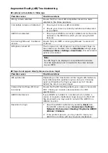
Page 53: ... location GNSS GPS connection fault Ensure that external GNSS connections and cabling are correct and fault free External GNSS GPS receiver in poor location For example Below decks Close proximity to transmitting equipment such as VHF radio Ensure GNSS GPS receiver has a clear view of the sky No Fix GNSS status icon is displayed GNSS GPS installation problem Refer to the installation instructions ...

Page 54: ... AIS hardware must be operational and connected to the same network as your MFD AR flags do not appear directly above on screen target Possible causes Possible solutions AIS update rate Depending on the classification of the target s AIS hardware transmitted position updates may be sent up to 3 minutes apart and therefore the flag may appear up to 3 minutes behind the actual onscreen target Camera...

Page 55: ...Chapter 11 Operation Chapter contents 11 1 Operation instructions on page 64 ...

Page 56: ...11 1 Operation instructions For detailed operation instructions for your product refer to the documentation that accompanies your display 81370 LightHouse 3 MFD Advanced Operation Instructions ...

Page 57: ...Chapter 12 Maintenance Chapter contents 12 1 Service and maintenance on page 66 12 2 Routine equipment checks on page 66 12 3 Product cleaning on page 66 ...

Page 58: ... perform the following routine checks on a regular basis to ensure the correct and reliable operation of your equipment Examine all cables for signs of damage or wear and tear Check that all cables are securely connected 12 3 Product cleaning Best cleaning practices When cleaning products Switch off power supply Use a clean damp cloth to wipe clean Do NOT use abrasive acidic ammonia solvent or oth...

Page 59: ...Chapter 13 Technical support Chapter contents 13 1 Raymarine product support and servicing on page 68 13 2 Learning resources on page 70 13 3 Operation instructions on page 70 ...

Page 60: ...e Homescreen The Getting started menu contains hardware and software information for your MFD 2 You can view further information about your MFD or view information about products networked using SeaTalkhs and SeaTalkng NMEA 2000 by selecting the Network tab then i to display detailed software information and your MFD s network IP address select your MFD from the list ...

Page 61: ...ii to display detailed diagnostics information for all products select Product info from the Diagnostics pop over menu ...

Page 62: ...Chapter 14 Technical specification Chapter contents 14 1 Technical specification on page 72 ...

Page 63: ...ew Zealand C Tick compliance Level 2 RoHS Directive 2011 65 EU WEEE Directive 2012 19 EU GNSS GPS receiver specification Signal acquisition Automatic Channels Simultaneously track up to 28 satellites Operating frequency 1574 MHz to 1605 MHz Update rate 10 Hz Sensitivity Cold start 147 dBm Re acquisition 160 dBm Tracking 164 dBm GNSS GPS satellite system compatibility GPS GLONASS Galileo ready Beid...

Page 64: ...enna Internal AHRS specification AHRS 3 Axis digital accelerometer 3 Axis digital compass 3 Axis MEMS Gyro digital angular rate sensor Magnetic compass accuracy Static 1 RMS Dynamic 3 RMS Pitch Roll and Yaw accuracy 1 Heading Pitch Roll and Rate of Turn update rate 10 Hz ...

Page 65: ...Chapter 15 Spares and accessories Chapter contents 15 1 Accessories on page 76 15 2 SeaTalkng cables and accessories on page 76 ...

Page 66: ... 8 ft Spur cable A06040 Used to connect device to the SeaTalkng backbone 2 1 x 2 m 6 6 ft Power cable A06049 Used to provide 12 V dc power to the SeaTalkng backbone 3 2 x Backbone terminators A06031 Terminators must be fitted to both ends of the SeaTalkng backbone 4 1 x 5 Way connector A06064 Each connector block allows connection of up to 3 SeaTalkng devices Multiple connector blocks can be daisy...

Page 67: ...llows connection of one SeaTalkng device Multiple T pieces can be daisy chained together 6 2 x Backbone terminators A06031 Terminators must be fitted to both ends of the SeaTalkng backbone SeaTalk to SeaTalkng converter kit E22158 consists of 1 1 x 2 m 6 6 ft Power cable A06049 Used to provide 12 V dc power to the SeaTalkng backbone 2 1 x 1 m 3 3 ft Spur cable A06039 Used to connect a device to th...

Page 68: ...g plugs A06032 Used to cover unused spur connections in 5 way blocks T piece connectors and SeaTalk to SeaTalkng converter 6 2 x Backbone terminators A06031 Terminators must be fitted to both ends of the SeaTalkng backbone SeaTalkng spur cables SeaTalkng spur cables are required to connect devices to the SeaTalkng backbone 1 SeaTalkng spur cables 0 4 m 1 3 ft Spur cable A06038 1 m 3 3 ft Spur cabl...

Page 69: ... ft Backbone cable A06037 SeaTalkng power cables SeaTalkng power cables are used to provide the SeaTalkng backbone with a single 12 V dc power source The power connection must include a 5 amp inline fuse not supplied 1 2 m 6 6 ft Power cable straight A06049 2 2 m 6 6 ft Elbow right angled power cable A06070 SeaTalkng connectors SeaTalkng connectors are used to connect SeaTalkng devices to the SeaT...

Page 70: ... A06048 Used to connect SeaTalk2 devices or networks to a SeaTalkng backbone 4 SeaTalkng to DeviceNet female adaptor cables connect NMEA 2000 devices that use a DeviceNet connector to the SeaTalkng backbone or connects SeaTalkng devices to an NMEA 2000 network The following cables are available 0 4 m 1 3 ft SeaTalkng to DeviceNet female adaptor cable A06045 1 m 3 3 ft SeaTalkng to DeviceNet female...

Page 71: ...10 0 4 m 1 3 ft DeviceNet female to stripped end adaptor cable E05026 11 0 4 m 1 3 ft DeviceNet male to stripped end adaptor cable E05027 ...

Page 72: ...26208 NMEA Command group function 126208 NMEA Acknowledge group function 126464 Transmission PGN List 126464 Received PGN List 126992 System time 126993 Heartbeat 126996 Product information 126998 Configuration information 127250 Vessel heading 127251 Rate of turn 127257 Attitude 129025 Position rapid update 129026 COG SOG rapid update 129027 Position delta high precision 129029 GNSS Position data...

Page 73: ...nce specification 72 Connecting SeaTalkng cables 39 Connections Battery 44 Distribution panel 43 Power 41 42 SeaTalkng 39 SeaTalkng power cable 42 Contact details 68 Current reading 53 D Deck mounting kit 33 Deviation 53 Diagnostics 69 Dis assembly 35 Distribution panel connection 43 Documentation 14 Operation instructions 14 70 E Electromagnetic Compatibility 26 EMC See Electromagnetic Compatibil...

Page 74: ...2 Connecting 39 Connecting cables 39 Connectors 79 Kits 76 LEN 39 41 Load equivalency number 39 41 Power 41 42 Power cables 79 Spur cables 78 System loading 42 SeaTalkng cables 76 Service Center 68 Servicing 10 66 Software updates 18 Specification GNSS GPS 72 Support forum 70 Surface mounting 31 33 System example typical system 40 T Technical specification 71 72 Technical support 68 70 Thermal bre...

Reviews: