M7 GX Technical Manual
18
Raveon Technologies Corp.
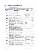
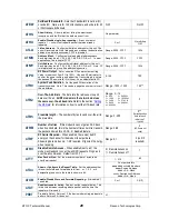
AT
HN
Channel Number
Select current radio channel number. This
command does not store the channel number into EEPROM,
Range: 1 - 6
1
AT
HP
Channel Number
– Select current radio channel number. The
channel number is stored in EEPROM memory.
Range: 1 - 6
1
AT
I0
Read/Set IO Mode
Normal digital serial mode is
5
. If plugged
into Tech Series enclosure, set this to
ATIO 8
for automatic IO
detection. Cycle Power to radio after changing ATIO mode.
MIMIC mode
ATIO 1
.
S, U, G, T, A
to force certain Tech Series
IO operation.
Range: 0-8
5
AT
JF
Read/set the CTS threshold
– Set the serial buffer threshold
where the CTS line is negated. By default the ATJF level is at
80% of the internal buffer size.
1
- 2000
3800
AT
L
Enable/Disable the LEDs
– 1 = LEDs always off. This reduces
some power consumption. 0 = LED operate normally.
0 or 1
0
AT
NB
Parity
– Selects parity format. Settings 0-4 transfer 8-bits over
antenna port and generate the parity bit on the RF receiving side.
Range: 0
– 5
0 = none
1 = Odd
2 = Even
3 = Mark (1)
4 = Space (0)
0
AT
NS
Stop Bits
–
Selects the number of stop bits.
Range: 1-2
1
AT
R1
Select CD pin output signal – CD may be RF carrier detect, or
modem data detect.
Range : 0 – 5
5 = GPIO
4 = Data Framing
3= Always negate CD
2 = Always assert CD
1 = Data CD
0 = RF CD
0
AT
R3
Serial Port Time Out – The time in milliseconds for the serial
port to time out. When data is entering the serial port, and this
amo0unt of time passes with no more data, the M6 will begin to
transmit the data over the air.
Range: 1 - 999
20
20mS is the
default.
AT
R8
Frequency Offset.
Used to adjust the radio on the center of the
radio channel. Offset in Hz, 120Hz resolution.
Range: -5000 to +5000
0
**
AT
RQ
Receiver Signal Level – Reads the Receiver Signal strength
this instant, and returns the level in dBm.
Range: -40 to –130
(dBm)
-
AT
RS
RSSI (Receive Signal Strength Indicator) – Returns the signal
level of last received packet. The reading is in dBm. Usable for
relative comparison of signals, but absolute value is within10dB
at -90dBm.
No parameters.
Returns a number : -
50 to –140 (dBm)
varies by model.
none
AT
SL
Electronic Serial Number
– Reads and returns a unique
electronic serial number for this unit.
Read Only
1 - 999999999
unique
AT
SM
LPM Operation Enable – When Low Power Mode (LPM) is set
to 1, the DTR input line controls the M6’s low-power operation.
When set to 0, the M6G will not go into LPM, regardless of the
state of the DTR pin. When set to 2, the modem is forced into a
low-power mode, disabling the receiver. When set to 4, the RX
is turned off, and the transmitter will still send data and GPS
position report.
Range: 0, 1, 2
0
AT
ST
Statistics
–
Show the unit’s operational statistics. See Statistics
section of user manual.
0, 1,2, 3, 4, or 5
None
AT
TD
Transmit Test Data
– When issued, the modem will begin
transmitting data. The type of data sent is set in the parameter.
Entering a <CR> will terminate the transmission.
0 = Go back to normal
1 = Random
3 = 1010… at ¼ baud rate
4 = TX all 0s
5 = TX all 1s

