System Planning
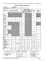
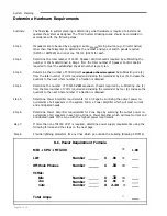
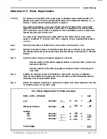
(LLM) lines and TC4120 (SCC25) Speaker Control lines needed. In the example, there are no
requirements for SCC25s, indicating that there are no single-link staff phones in the system.
However, the example does require, 47 LLM lines (5 for the System, 1 for the Display Phone,
6
for the Trunks/COAs, 5 for the
3 Key
Phones, 10 for the Administrative Phones, and 20 for
the Staff - C locations). Note that in this example, all three key phones get the same five line.
If each of the three key phones had one unique line, they would require 7 LLM lines (4
common and 3 unique lines).
Speaker equipment is required to support one-way communication paths for paging, time-
zone signals, and other functions. The amount of hardware required is determined by the
total number of TC4110 (SC25) Speaker Control lines needed. In the example system, 43
Speaker SC25 lines are required: 8 lines for the 8 Staff - A locations, 15 lines for the 15 Staff -
B locations, and 20 lines for the 20 Staff - C locations.
(Note:
When determining SC25 and
SCC25 requirements, do not exceed 2 amps A.C. (5OW) through any single SC line.)
PHYSICAL (Phys. #): This is
where you list the set of physical numbers (P:) which will support each
NUMBER:
Function. Except for Key Phones and the TC4400 Call Control Console, the physical number
range must be equal to the figure in the Quantity column. Physical numbers for Key Phones
must be equal to the number of unique lines required. The System (P:O - 4) and Display
Phone (P:5) physical numbers are standardized and should not be changed. Physical number
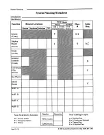
assignments for the example system are: Trunks/COA’s (P:6 - 1 l), Key Phones (P: 12 - 16), Ad-
ministrative Phones (P:17 - 26), Staff-A (P: 16 - 23), Staff - B (P:47 - 61), and Staff - C (P:27 -
46).
The system software uses physical numbers to keep track of the equipment
connected
to
each line and to access attribute programming on how each line should be handled (see KI-
1584 for the programming associated with physical numbers).
Assigning
physical numbers is
one of the most complex and important parts of system design. The following paragraphs de-
scribe the mechanics of assigning physical numbers.
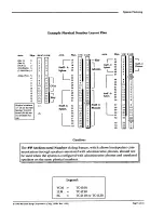
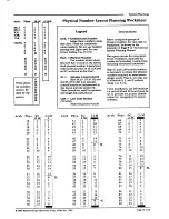
Physical numbers relate to pins on the SC25 and SCC25 (SC) and TC4150 LLM boards. They
are assigned in groups of consecutive numbers which provide the required overlap
between
LLM
and SC boards. This overlap is required when speakers and phones are placed at a staff
location and required to work as a unit. However, when a multi-link phone is used without a
speaker, the
speaker circuit may be used elsewhere for paging and zone-signalling. In
the
example, physical numbers 17 - 23 overlap in this manner (P: 16 - 23 are used for Staff A
corridor speakers and
P:
17 - 26 are used for Administrative Phones).
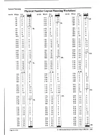
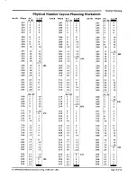
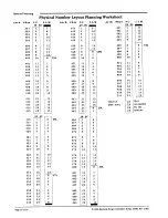
A
Physical Number Layout Planning Worksheet is
provided at the back of this manual. It
shows every physical number in the system and the relationship between physical numbers
and pin numbers on LLM and SC boards. The
Example Physical Number Layout Plan
on
the
facing page shows these relationship for the example system. (Shaded bars have been
drawn to show relationships at a glance. This could also be accomplished using colored
pencils, to mention but one option.)
CABLING:
In this column, the type of cabling required between remote locations and the Telecenter
cabinet is noted. Where possible, standard cable requirements are predesignated. Cabling for
Key Phones is instrument dependent, as is cabling for Administrative and Staff functions.
Cable types are noted according to the legend at the bottom right of the worksheet. (
A
for a
shielded pair,
B
for 3 conductors with a shield, C for a twisted pair, and
D
for 3 shielded
pairs). Cabling requirements
can be determined using the
Riser Diagram
(KMO895).
DISPLAYS: The box
at the bottom of the worksheet provides space for recording TM432 Graphics An-
nunciator Module (GAM) and TC4200 Vacuum Fluorescent Display (
VFD)
requirements.
These requirements are separately itemized because they do not require communication lines
from either Line-Link Modules or Speaker Control Boards.
Page 4 of 16 1989 Rauland-Borg Corporation (Orig. 10/88; Rev. l/89)


