Measurement Principles
R&S
®
RT
‑
ZD10/20/30
49
User Manual 1410.4550.02 ─ 05
6.2.2
Signal Loading for Non-Differential Input Signals
Chapter 5, "Characteristics of Differential Probes"
various types of input signals can be measured with a differential probe. Every
type of input signal has an associated input impedance.
●
For differential input signals, the input impedance of the probe is the impe-
dance between its positive and negative signal sockets.
●
For single-ended input signals, the input impedance is the impedance
between the positive or negative signal socket and the ground socket.
●
For common mode input signals, the input impedance is the impedance
between the parallel connection of the positive and negative signal sockets
and the ground socket.
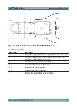
The equivalent circuit diagram in
can be used to determine the associ-
ated input impedance. The
provides as an example the DC input resist-
ance for several input signals.
Table 6-3: DC Input Resistance for Various Input Signals
Type of input signal
Differential
Single-ended
Common mode
Input Resistance
1 MΩ
500 kΩ
250 kΩ
This table shows that common mode signals suffer the highest loading. This char-
acteristic of all differential probes is particularly bothersome because common
mode signals frequently have a very high source resistance (e.g. 10 kΩ for con-
ventional fail-safe circuits). While the input resistance achieved for common mode
voltages with the R&S
RT
‑
ZD10/20/30 differential probe remains sufficiently high,
probes with lower input resistances can lead to unfavorable loading effects.
6.3
Probing Philosophy
The previous sections explained that probes exert a load on the signal to be mea-
sured and change its characteristic. The signal at the test point where the probe
makes contact (V
in
) is therefore different from the signal that was present before
the probe was connected (V
S
). This effect cannot be avoided and occurs with all
real probes – independent of type and manufacturer.
Probing Philosophy

