R&S
RT
‑
ZA15 External Attenuator
R&S
®
RT
‑
ZD10/20/30
29
User Manual 1410.4550.02 ─ 05
Adjustment
●
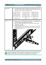
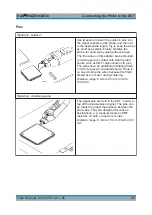
Using the adjustment tool, turn the trimmer for pulse response of the
positive input on the external attenuator until an optimum square wave
response is visible on the oscilloscope screen.
Setup and adjust-
ment
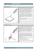
Repeat the procedure to adjust the pulse response of the negative input:
●
Using the lead, connect the positive input of the external attenuator to
the ground clamp of the R&S RTO oscilloscope.
●
Press the negative input directly to the square wave signal clamp.
●
Trigger level = -500 mV
Trigger slope = Negative
●
Using the adjustment tool, turn the trimmer for pulse response of the
negative input until an optimum square wave response is visible on
the oscilloscope screen.
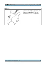
Keep the adjustment of the positive and negative input as symmetric as
possible to ensure a good common mode rejection for AC signals.
Adjusting

