


Measurement Principles
R&S
®
RT
‑
ZD10/20/30
48
User Manual 1410.4550.02 ─ 05
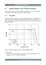
6.2.1.2
Input Capacitance C
dm
The input capacitance C
dm
causes the input impedance to decrease in the
medium-frequency range (100 kHz to 1.0 GHz). It affects the settling time of the
input voltage in the case of fast transients.
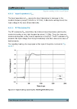
6.2.1.3
RF Resistance R
RF
The RF resistance R
RF
determines the minimum input impedance and thus the
maximum loading at very high frequencies above 1.0 GHz. Thus, the measure-
ment result depends on the source impedance of the DUT. The RF resistance R
RF
prevents the input voltage from rising immediately to its final value in the case of
fast transients.
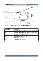
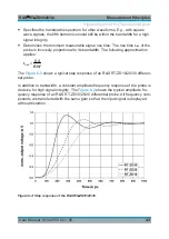
The resulting loading of a step signal at the input of the probe is shown in
.
Figure 6-7: Signal loading caused by the R&S
RT
‑
ZD10/20/30 probe
Signal Loading of the Input Signal