background image

Instrument control

R&S

®

AREG800A

53

Getting Started 1179.3609.02 ─ 02

7.3.1


Additional display characteristics

The following section provides a short insight on the indication of the screen in
general, and significant elements that you see under specific operating modes, in
dialogs or settings.

Appearance of active elements

Active

 elements like On/Off switches, state buttons have a 

blue

 back-

ground.

Selected

 elements are framed or highlighted 

orange

.

Inactive

 elements are 

gray

.

On-Screen keypads

As additional means of interacting with the instrument without having to con-
nect an external keyboard, either a numerical or alphanumerical on-screen
keypad appears when you activate an entry field (see 

Chapter 7.5, "Entering

data"

on page 55).

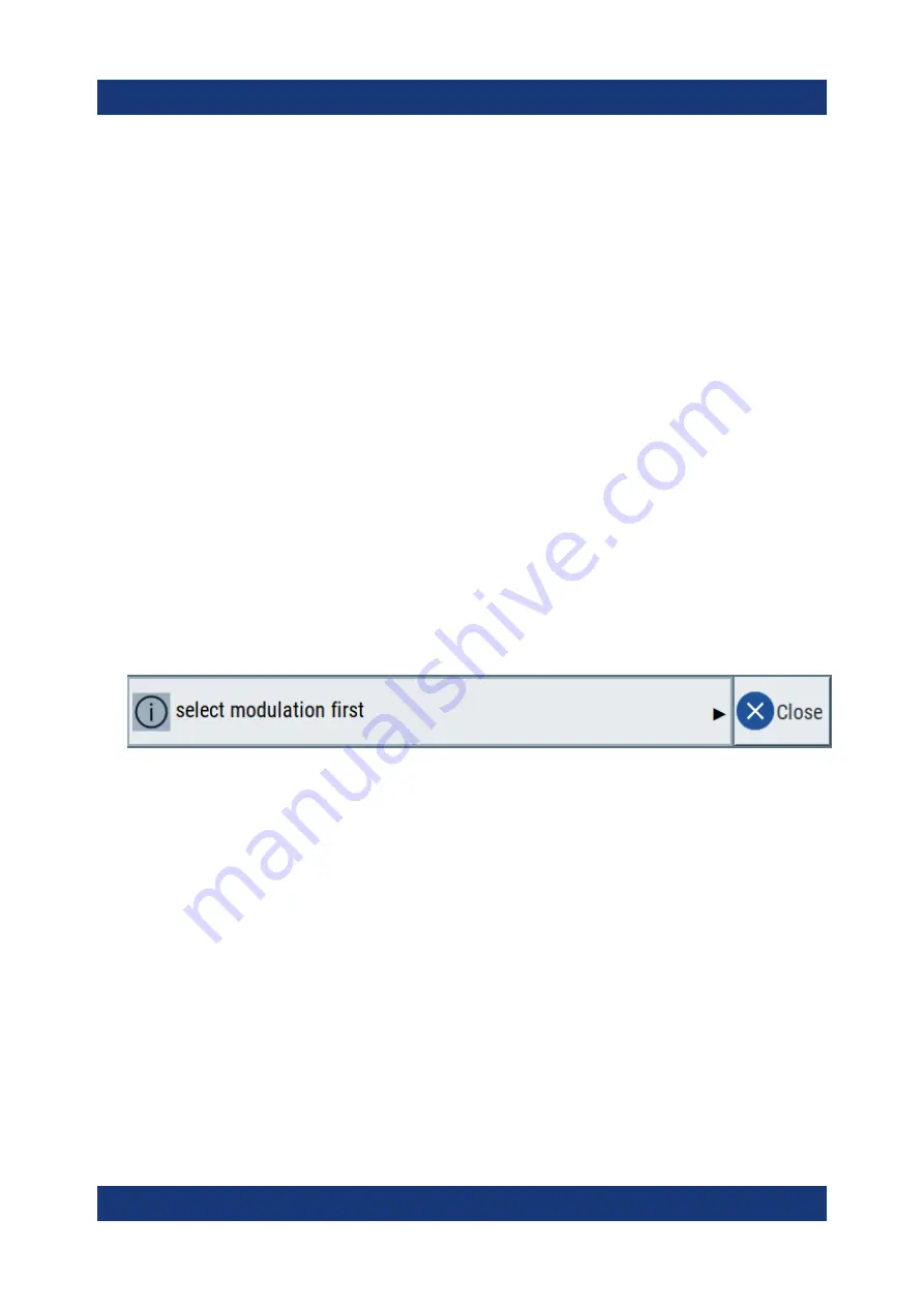
Info line

The "Info line" shows brief status information and error messages. It appears
when an event generates a message. If selected, the R&S


AREG800A shows

information on static errors and the error history.

Key parameters indicated in tab labels

Most dialogs are divided into tabs with logically grouped parameters. The tab
label expresses the content and can also contain status indicators or the set
value of a key parameter.

Scroll bar handle

An arrow icon that appears when you touch a scroll bar helps you to scroll in a
dialog or list.

Progress indicators

A busy icon indicates a currently running process. If a process takes some
time, a progress bar shows the current state.

Context-sensitive menus

Within the entire screen display, including single parameters, you can access
context-sensitive menus that provide some additional functions.

Understanding the display information

Summary of Contents for AREG800A

Page 1: ...R S AREG800A Automotive Radar Echo Generator Getting Started 1179360902 Version 02 T92...

Page 2: ...ww rohde schwarz com Subject to change data without tolerance limits is not binding R S is a registered trademark of Rohde Schwarz GmbH Co KG Trade names are trademarks of the owners 1179 3609 02 Vers...

Page 3: ...ons 11 2 4 Data sheet 12 2 5 Release notes and open source acknowledgment OSA 12 3 Key features 13 4 Preparing for use 15 4 1 Lifting and carrying 15 4 2 Unpacking and checking 15 4 3 Choosing the ope...

Page 4: ...atic operation setups 45 6 2 Saving and recalling settings 47 7 Instrument control 51 7 1 Possible ways to operate the instrument 51 7 2 Means of manual interaction 52 7 3 Understanding the display in...

Page 5: ...same information is provided in many languages as printed Safety Instructions The printed Safety Instructions are delivered with the product Throughout the documentation safety instructions are provid...

Page 6: ...ot waterproof Water that enters can electrically connect the casing with live parts which can lead to elec tric shock serious personal injury or death if you touch the casing If Rohde Schwarz provides...

Page 7: ...fuse Only use the power cable delivered with the product It complies with country specific safety requirements Only insert the plug into an outlet with protective conductor terminal Only use intact ca...

Page 8: ...nd This connection protects you against electric shock if an electric problem occurs 1 2 Labels on R S AREG800A Labels on the casing inform about Personal safety see Connecting to power on page 7 Prod...

Page 9: ...dous situation Could result in death or serious injury if not avoi ded CAUTION Potentially hazardous situation Could result in minor or moderate injury if not avoided NOTICE Potential risks of damage...

Page 10: ...Safety and regulatory information R S AREG800A 10 Getting Started 1179 3609 02 02 Warning messages in the documentation...

Page 11: ...instrument modes and functions It also provides an introduction to remote control a complete description of the remote control commands with programming examples and information on main tenance instru...

Page 12: ...s and their order numbers and optional acces sories 2 5 Release notes and open source acknowledg ment OSA The release notes list new features improvements and known issues of the cur rent firmware ver...

Page 13: ...Simulation of echoes of stationary and highly dynamic objects Simulation of echoes with extremely short object distances Simulation of echoes of multiple independent objects IF signals with high inst...

Page 14: ...Key features R S AREG800A 14 Getting Started 1179 3609 02 02...

Page 15: ...handles at the front are only for pushing and pulling the instrument when mounting in a rack see Chapter 4 4 2 Mounting the R S AREG800A in a rack on page 17 4 2 Unpacking and checking 1 Unpack the R...

Page 16: ...vironments Environments that are directly connected to a low voltage supply network that supplies residential buildings Class A equipment is intended for use in industrial environments It can cause ra...

Page 17: ...oo many products 3 NOTICE Overheating can damage the product Prevent overheating as follows Keep a minimum distance of 10 cm between the fan openings of the prod uct and any object in the vicinity Do...

Page 18: ...k 4 Tighten all screws at the rack brackets with a tightening torque of 1 2 Nm to secure the R S AREG800A in the rack To unmount the R S AREG800A from a rack 1 Loosen the screws at the rack brackets 2...

Page 19: ...S QAT100 and available under material number 1142 5889 00 How to To connect to SMA on page 23 Use the cables TRX CRTL Cable IF TX CBL and IF RX CBL for connection of the instrument and the TRX fronte...

Page 20: ...el of the instrument Only use the AC power cable delivered with the R S AREG800A 2 Plug the AC power cable into a power outlet with ground contact The required ratings are listed next to the AC power...

Page 21: ...etwork LAN in the user manual 4 8 Connecting USB devices You can connect or disconnect all USB devices from the R S AREG800A during operation To connect USB storage devices USB storage devices such as...

Page 22: ...S AREG800A can generate radar signals when connected to an external frontend e g the R S QAT100 This section provides information on relevant connections between R S AREG800A and the R S QAT100 To pr...

Page 23: ...follows a Carefully align the connector of the cable and the connector along a com mon axis b Mate the connectors along the common axis until the male pin of the inner connector engages with the fema...

Page 24: ...own the product on page 28 2 Disconnect the SMA connections between R S AREG800A and R S QAT100 a Untorque the nut using a calibrated torque wrench Hold the opposite con nector part stationary with a...

Page 25: ...R S AREG800A and the TRX frontend with the IF TX CBL IF RX CBL cables 1 Take the IF TX CBL cable delivered with the TRX frontend See To check the serial number of the cables on page 27 2 Connect the T...

Page 26: ...ontrol cable at the Control connector at the base unit The sleeve locks 6 Plug the control cable at the Control connector at the TRX frontend The sleeve locks 7 NOTICE Excessive bending can damage the...

Page 27: ...y with a spanner b Turn the nut of the outer connector until the connectors are detached 3 To disconnect the TRX CRTL Cable a Hold the connector at the sleeve b To release the lock pull the sleeve wit...

Page 28: ...R S AREG800A boots When starting for the first time the R S AREG800A starts with the default settings When restarting the instrument the settings depend on the instru ment configuration before shut do...

Page 29: ...y To disconnect from power The R S AREG800A is in the standby state 1 NOTICE Risk of data loss If you disconnect the product from power when it is in the ready state you can lose settings and data Shu...

Page 30: ...Preparing for use R S AREG800A 30 Getting Started 1179 3609 02 02 Switching on or off...

Page 31: ...on the R S AREG800A are described in Chapter 1 2 Labels on R S AREG800A on page 8 5 1 Front panel tour This section provides an overview of the control elements and connectors on the front panel of th...

Page 32: ...ng information and allows you to quickly reconfigure the signal flow The screen is touch sensitive offering an alternative means of user interaction for quick and easy handling of the instru ment The...

Page 33: ...hapter Cleaning in the user manual for cleaning the touchscreen 5 1 2 Keys 5 1 2 1 Utility keys The utility keys cause the R S AREG800A to return to a defined instrument state and provide information...

Page 34: ...ff Opens and closes the Objects dialog In particular selects the Channel x tab of the first available radar channel RF On Off Activates and deactivates all available radar objects of all radar channel...

Page 35: ...current operation Table 5 4 Editing keys Type of key Description Esc key Closes all kinds of dialog boxes if the edit mode is not active Quits the edit mode if the edit mode is active In dialog boxes...

Page 36: ...dialog box move the cursor In a list scroll forward and backward through the list entries In a table move the selection bar horizontally In windows or dialog boxes with horizontal scrollbar move the...

Page 37: ...pter 4 8 Connecting USB devices on page 21 Sensor Connector for R S NRP sensors The connector is a six pole ODU Mini Snap series B connector A power sensor is connected to the R S AREG800A by insertin...

Page 38: ...02 1 2 3 Figure 5 3 R S AREG800A rear panel 1 Connectors for control synchronization and multi purpose signals page 39 2 Power switch power supply monitor LAN and USB connectors page 41 3 Digital IO...

Page 39: ...trol page 40 4 Sync In Sync Out page 40 5 Ext Clk In page 40 6 Ref In Ref Out page 40 7 User x page 40 8 IEEE 488 page 40 Control Four propriety bus connectors Control 1 to Control 4 for control of TR...

Page 40: ...BNC connectors for 10 MHz reference signals How to Chapter 4 10 Connecting to Ref In Ref Out on page 24 User x BNC multipurpose connectors for defining input signals and output signals For future use...

Page 41: ...a LAN for remote control remote operation and data transfer How to Chapter 4 7 Connecting to LAN on page 20 USB Two female USB universal serial bus 3 0 connectors of type A You can connect devices lik...

Page 42: ...B9 Digital IO DD Digital I Q connectors Digital IO DD 1 to Digital IO DD 4 provided for future use one connector per instrument board R S AREG8 B9 Aux IF In SMA female connectors Aux IF In 1 and Aux...

Page 43: ...IF signal from the external frontend to the R S AREG800A Rx two connectors per instrument board R S AREG8 B9 How to To connect to SMA on page 23 Tx IF In SMA female connectors Tx IF In 1 and Tx IF In...

Page 44: ...Instrument tour R S AREG800A 44 Getting Started 1179 3609 02 02 Rear panel tour...

Page 45: ...onnecting the R S QAT100 on page 22 The R S AREG800A is manually operated via the touchscreen Try out the following Configuring static operation setups 45 Saving and recalling settings 47 6 1 Configur...

Page 46: ...02 02 4 Click Apply The settings are applied To specify the radar channel bandwidth 1 In the tile diagram select Operation Setup Bandwidth Config 2 Set the bandwidths of the radar channels e g Bandwid...

Page 47: ...ve the instrument settings in a file To save the instrument settings in a file We assume a test configuration as described in Chapter 6 1 Configuring static operation setups on page 45 1 Press the Set...

Page 48: ...ttings so you can check that the stored user settings are restored afterwards 2 Press the Setup key on the front panel 3 In the Setup menu select Settings Save Recall 4 In the Save Recall dialog selec...

Page 49: ...not have enough informa tion on the changed settings In such case it is useful to visualize all param eters that have been changed from their default state Try out the following Touch and hold a spot...

Page 50: ...Trying out the instrument R S AREG800A 50 Getting Started 1179 3609 02 02 Saving and recalling settings...

Page 51: ...and rotary knob or an optional mouse and or keyboard The following description shows how to operate the instrument manually Remote control Create programs to automatize repeating settings tests and me...

Page 52: ...y knob The front panel provides nearly all functions and controls to operate the instru ment in the classic way without touchscreen Optional mouse and or keyboard These devices work like known from PC...

Page 53: ...5 Entering data on page 55 Info line The Info line shows brief status information and error messages It appears when an event generates a message If selected the R S AREG800A shows information on stat...

Page 54: ...s functions and settings can be accessed by selecting one of the following elements System and function keys on the front panel of the instrument Taskbar softkeys on the touchscreen Context sensitive...

Page 55: ...ight corner Press the Esc key on the front panel Drag and drop a minimized dialog from the taskbar to the tile diagram To select an option in a dialog box Tap the required option 7 5 Entering data Som...

Page 56: ...is added to the entry Tip For quick unit change you can enter shortcuts e g for a frequency value 1e8h for 100 MHz For an overview of shortcuts supported by the R S AREG800A see chapter Unit Shortcut...

Page 57: ...Getting information and help In some dialog boxes graphics are included to explain the way a setting works For further information you can use the following sources Tooltips give the value range of t...

Page 58: ...key on the front panel If a dialog box is opened the help topic for the current tab is shown Other wise the Contents page appears Navigating in the table of contents and in the help topics 1 To move...

Page 59: ...to working with the R S AREG800A interactively located directly at the instrument it is also possible to operate and control it from a remote PC The R S AREG800A supports various methods for remote c...

Page 60: ...instrument Thus remote operation of the instrument is possible Instrument control from a remote computer To access the basic utility functions of the R S AREG800A perform a right mouse click the block...

Page 61: ...duct contact our customer support center A team of highly qualified engineers provides support and works with you to find a solution to your query on any aspect of the operation program ming or applic...

Page 62: ...Contacting customer support R S AREG800A 62 Getting Started 1179 3609 02 02...

Page 63: ...g boxes 54 Display Active elements 53 Context sensitive menu 53 Info line 53 Information 52 On screen keypad 53 Tab labels 53 E Emulating front panel keys 60 G Getting started 11 H Help 11 57 I Info l...

Page 64: ...peration Manual 52 Output connector 40 P Parameters Entering 56 57 Placing on a bench top 16 Power Connecting the instrument 20 Power on Key 33 Power supply Connector 41 Preparing for use 15 Connectin...

Reviews: