Documentation Center
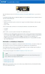
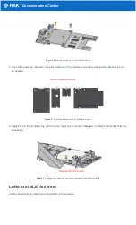
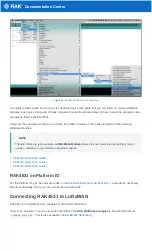
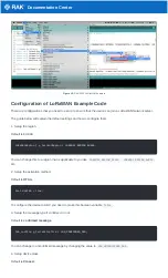
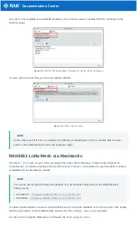
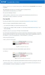
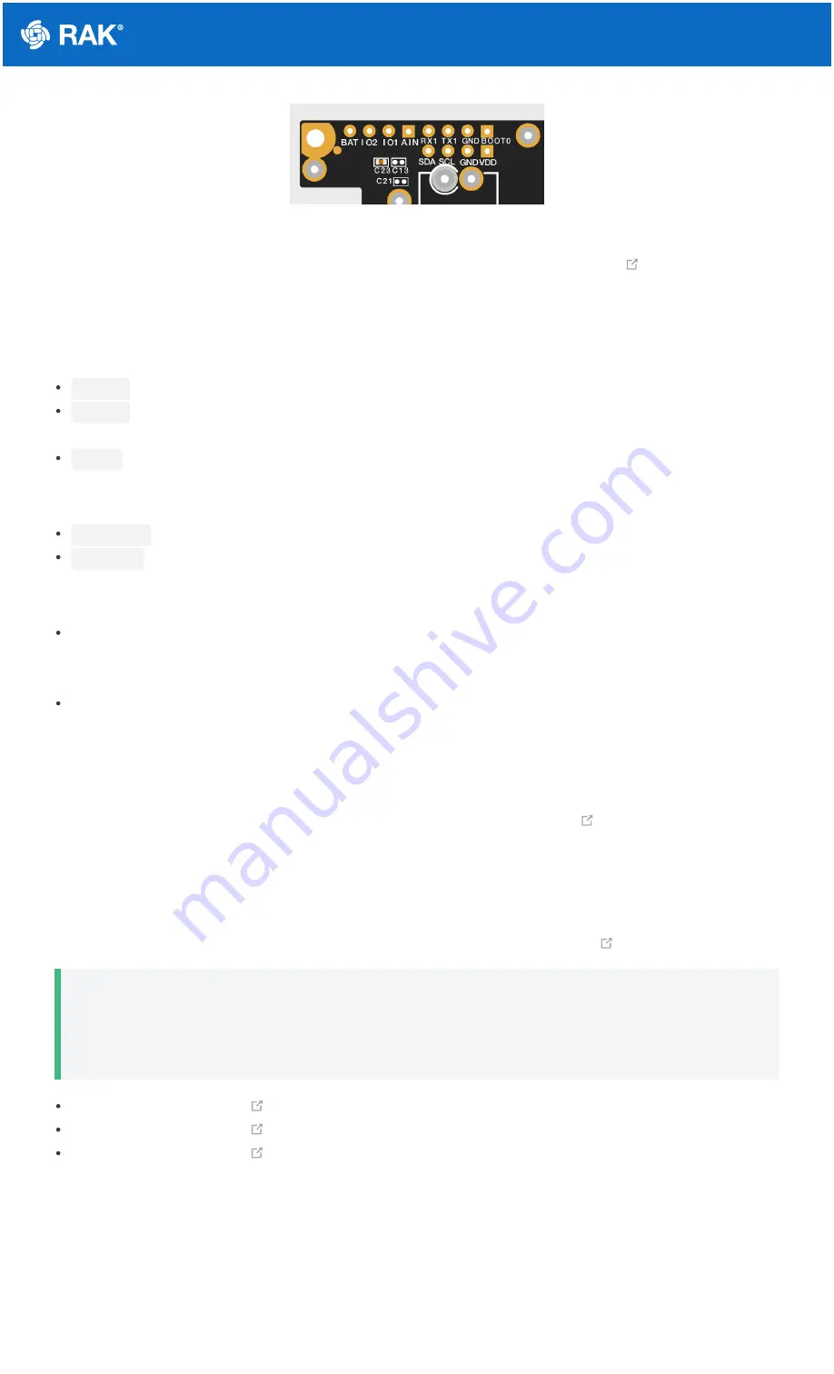
Figure 2: WisBlock Base exposed pins
More information can be found on the
official documentation of the specific WisBlock Base
you used in your
project.
For RAK5005-O WisBlock Base with RAK4631 WisBlock Core, the accessible GPIO pins are defined as follows in
the Arduino IDE and Platform IO:
WB_IO1
for IO1 pin
WB_IO2
for IO2 pin (Also used to control the 3.3 V supply of some WisBlock Modules to achieve low-power
IoT devices.)
WB_A0
for AIN
There are usable LEDs as well that can be controlled by the RAK4631 on the WisBlock Base board:
LED_GREEN
LED_BLUE
UART1 and I2C_1 are also exposed on the header of the WisBlock Base board.
RAK4631 has a native USB peripheral onboard (Serial), which is used for programming and Serial debugging
and two usable hardware UART1 and UART2 (Serial 1 and Serial 2). UART1 is accessible to WisBlock Slot A,
WisBlock IO slot, and the exposed header pins. UART2 is accessible only on the WisBlock IO slot.
The I2C_1 header pins are as well shared to the WisBlock Base Slots A to D. The second I2C_2 is available
only on the WisBlock IO slot.
RAK4631 to WisBlock Modules
RAK4631 WisBlock Core is designed to be interfaced with other
like sensors, displays, and
other interfaces. You need to connect these modules to the compatible slots on the WisBlock Base.
Each WisBlock Modules that will be used with RAK4631 WisBlock Core have a dedicated quick start guide you
can follow on how to connect to the WisBlock Base.
Listed are the quick start guide of some
WisBlock modules you can buy from our store
📝
NOTE
The listed links are just examples. All WisBlock Modules have their own quick start guide that you can
use as a reference to get started on specific modules.
RAK1901 Quick Start Guide
RAK1902 Quick Start Guide
RAK1903 Quick Start Guide
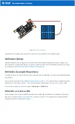
Figure 3 shows an illustration on how you can combine various WisBlock Modules with the RAK4631 WisBlock
Core via the WisBlock Base board.

