Install the connecting wire in as straight a line as possible. If you must make a turn or bend in the
wire, make the turn in a sweeping curve with a minimum radius of eight inches and a minimum
included angle of 90°.
To minimize resistance, the copper wire must be pre-welded to the grounding rods/plates, or
welded to the rods/plates using an exothermic welding process at the site.
Make sure all welds are secure before burying the grounding rods. Rods and plates with welded
joints do not need periodic visual inspection and can be fully buried (no valve box required).
Measure the ground resistance around the grounding system after installation, and once every
year after that.
NOTE:
The ground wire from the equipment to the grounding system should be as short as possible
and have no bends, kinks, or coils in the wire.
Inspect the grounding system’s clamped connections to the equipment (not the welded
grounding system connections) once a year to make sure they are secure and corrosion-free.
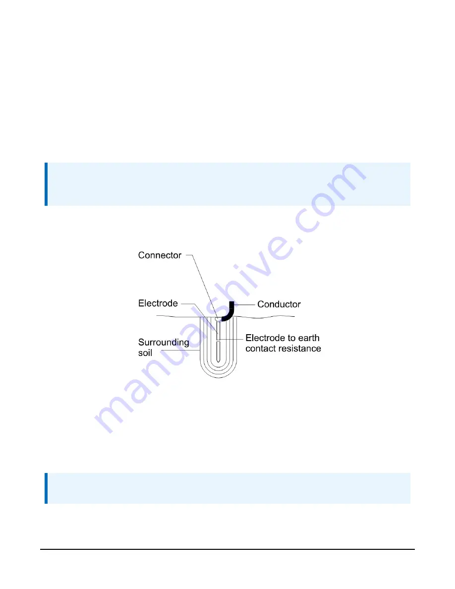
FIGURE A-1. Grounding systems can develop resistance at many points
A.1.3 Ground rod stacking
(p. 82)) are ground rod splices. If a single grounding
rod fails to produce 10-ohm ground resistance (maximum), threaded couplers can be used to
“stack” grounding rods.
NOTE:
Use threaded couplers made of the same material as your grounding rods.
Section Appendix A. Grounding recommendations
81
Summary of Contents for WS-PRO2
Page 9: ...FIGURE 3 4 WS PRO2 bottom layer Section 3 Initial inspection 5...
Page 113: ......


