RAIMONDI BULLDOG ADV Use And Maintenance Manual Download Page 26

mod. BULLDOG ADV - eD. 03/2014 - s. 04

©  Raimondi S.p.a.

Chapter 4

Use of the commands

Page 26/44-4

machines & tools for the tile & stone professional

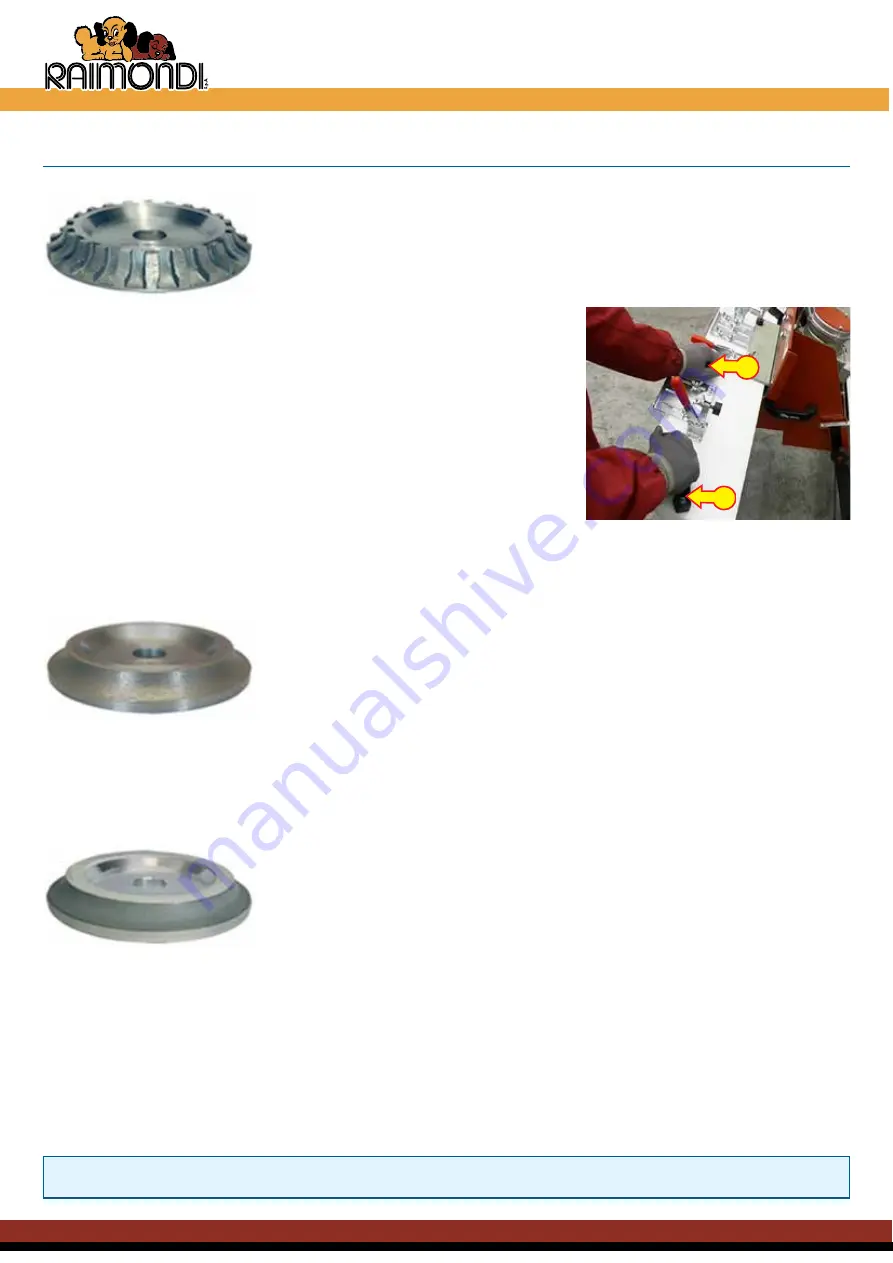
  4.5  half-bullnose shaping

Shaping phase (removal of the 90° angle and creation of the quarter round profile)

Suitable to cut bullnose up to 30 mm (1 

3/16”

) of maximum thickness.

1)

  Press the switch to turn on the machine.

2)

  Wait for cooling water.

3) 

Start your work grasping knob (

A

) with your left hand and handle (

B

)    

  on the carriage with your right. 

4)

  Proceed with shaping by pushing the carriage slowly forward towards   

  the grinding wheel.


5)

  Continue the cut maintaining a constant speed.

6)

  Slow down towards the end of the cut.

7)

  If the materials is very hard or thick, repeat the shaping in 2 or 3 passes.

8)

  Every 50 linear metres 

(164’)

 shaped, check condition of the grinding   

  wheel profile.

9)


Wear may alter the profile of the grinding wheel and lead to incorrect    

Grinding / Finishing phase

To grind / finish the profile previously created with the grinding wheel:

1)

  Use a grinding wheel with the same radius as that of the grinding wheel used for removal. 

2)

  Perfect positioning of the grinding wheel so that it copies the shape previously created.

3)

  The amount of material removed should not exceed 2/10 of mm (0,008 inches).

B

Polishing phase

Before polishing, it is essential to perform the grinding / finishing operations

In order to maintain the grinding wheels in good working condition: 

1)


Use a grinding wheel with the same radius as that of the grinding wheel used previously for grinding / finishing.

2)

  Perfect positioning of the grinding wheel so that it copies the shape previously created.

3)

  The grinding wheel must maintain minimum contact with the material. The amount of material removed should not exceed 

1/100 of mm (0,00004 inches).

4)

  Cooling water must be clean. Suspended dust resulting from the operations previously performed may damage the 

diamond rib.

5)

  The grinding wheel operating cycle is the following: 400 grain, 800 grain, 1500 grain, 1800 grain, 3500 grain.

ThE PASSAGE FrOM A GrAIN TO ANOThEr ShALL BE GrADUAL AND COMPLY WITh ThE rECOMMENDED 

PrOCEDUrE.

A

  shaping.This will prevent correct execution of the subsequent stages of operation, namely grinding and polishing. To  

  regenerate the grinding wheel profile, contact an authorised dealer. 

Summary of Contents for BULLDOG ADV

Page 1: ...Use and maintenance manual www raimondiutensili it BULLDOG ADV...

Page 2: ...__________________________________________________________________________ 18 44 3 Chapter 4 Use of the commands 4 1 Adjusting the grinding wheel for half round shaping________________________________...

Page 3: ...industry Intended use IS IN CONFORMITY WITH THE REQUIREMENTS Directive 2006 42 ec of the European Parliament and of the Council of 17 may 2006 on machinery and amending directive 95 16 ec in addition...

Page 4: ...not complying with the specifications of RAIMONDI S p A if purchased or not supplied by RAIMONDI S p A if manufactured by it as well as improper use of the machine will make the warranty null and void...

Page 5: ...S STRICTLY FORBIDDEN 1 3 Intervention request Technical Service Each intervention request to the Technical Service shall be sent by fax to RAIMONDI S p A Technical Service Telefax 39 059 282 808 E mai...

Page 6: ...function and position of the STOP and START buttons 11 Replace parts deemed to be broken with original spare parts warranted by the manufacturing company 12 Never try reckless solutions 13 Any interv...

Page 7: ...orrect use of the machine BULLDOG ADV profiling machine is suitable for profiling edges on single and double fired ceramic tiles porcelain gres marble natural stone Tuscan terracotta tiles cement aggl...

Page 8: ...32 1 3 16 mm 8 10 15 20 30 HALF BULLNOSE GRINDING inches 5 16 3 8 19 32 25 32 1 3 16 FINISHING mm 8 10 15 20 30 BULLNOSE POLISHING inches 5 16 3 8 19 32 25 32 1 3 16 V 45 JOLLYCUT BEVELLING MITERING45...

Page 9: ...47 1 4 trolley see the accessories chapter 5 6 2 5 Description of machine groups TheBULLDOGADVseriesaremadeupofaseriesofgroups Theseinteracttoensurefunctionsarealwayseffective Thegroupsare 1 Motor gro...

Page 10: ...D ON EXCLUSIVELY WHEN THE OPERATOR IS IN THE WORKING POSITION THE MACHINE SHALL BE TURNED OFF AT THE END OF EACH CUTTING OPERATION getting the hands close to the grinding wheel while it is running is...

Page 11: ...e level Obviously sound pressure varies in relation to the type of blade its wear status and the material to be cut hence we have made a series of measurements using different types of blades and diff...

Page 12: ...ations In any case these are associated to relevant factors such as the type of material to be cut and wear of the disc The results of the measurements carried out in the field implementing UNI EN ISO...

Page 13: ...al positioning and removal thereof once split up shall be taken into account RAIMONDI S p A believes BULLDOG ADV shall be included in the group of machines not exceeding the limit values provided for...

Page 14: ...s in electrical and electronic equipment DIRECTIVE 2002 96 EC WEEE Directive of the European Parliament and of the Council of 27 January 2003 on waste electrical and electronic equipment With referenc...

Page 15: ...suitable capacity 200 Kg 441 lbs MAKE SURE THE TROLLEY HAS BEEN REMOVED THE TOOL BOX EQUIPPED WITH THE SPECIFIC SAFETY PIN HAS BEEN BLOCKED AND THE WATER TANK HAS BEEN EMPTIED 3 2 Manual handling Manu...

Page 16: ...ive ground cable In case of doubt do not connect the machine Connect the machine to a 16A socket THE USE OF EXCESSIVELY LONG PATCH CORDS OR POWER SUPPLY WITH CURRENT GENERATORS MIGHT LEAD TO THE FOLLO...

Page 17: ...XED CORRECTLY Free the front legs by completely unscrewing the leg fixing knobs A Go to the front side of the machine and lift it so that the leg goes past the left and right safety bars B and at this...

Page 18: ...ean water into the tank until a level 2 cm 3 4 above the recycle pump has been reached 3 4 1Tank filling TO CARRY OUT THIS OPERATION MAKE SURE THE MACHINE IS NOT CONNECTED TO THE MAINS TO ALLOW FOR TH...

Page 19: ...adjustments repeating the previously illustrated steps Horizontal adjustments Vertical adjustments F D E L M G A E D Insert the wrench A in the nut for vertical adjustment Place the materiel to be pr...

Page 20: ...or group by slackening the B and C handles Insert the wrench G in the nut for vertical adjustment and screw until the grinding wheel height E slightly exceeds the thickness of the material to be cut P...

Page 21: ...f 800 mm 31 1 2 and a width determined by the following configurations width ranging from 100 mm 3 15 16 to 200 mm 7 7 8 with short or long guides and black square width ranging from 70 mm 2 49 64 to...

Page 22: ...with a width ranging from 70 mm 2 49 64 to 100 mm 3 15 16 Position the material to be shaped onto the trolley perfectly rested against the frame slide E and against the rear support F of trolley Loose...

Page 23: ...ce R P Q R Position the material to be shaped onto the trolley perfectly rested against the frame slide E and against the rear support F of trolley Loosen side knobs O and extract steel square from be...

Page 24: ...In order to prevent the material from shifting draw the black square G near it and lock it by knobs H B F E G H BEFORE STARTING PROCES SING MAKE SURE THAT THE PRESSING DEVICE OR CLAM PS I DO NOT INTE...

Page 25: ...ORE PROFILING MAKE SURE THE KNOB AND THE HANDLE ON THE TROLLEY HAVE BEEN PROPERLY FIXED THE FEEDING SPEED DURING THE PROFILING SHALL BE PROPORTIONAL TO the HARDNESS AND THICKNESS OF THE MATERIAL TO BE...

Page 26: ...t of the grinding wheel used for removal 2 Perfect positioning of the grinding wheel so that it copies the shape previously created 3 The amount of material removed should not exceed 2 10 of mm 0 008...

Page 27: ...elt 4 6 Performing Jolly cuts mitering 45 and bevelling Removal phase Suitable for Jolly cutting mitering 45 and bevelling 1 Adjust the position of the grinding wheel according to the quantity of mate...

Page 28: ...ing water must be clean Suspended dust resulting from the operations previously performed may damage the diamond belt 4 The belt operating cycle is the following 400 grain 800 grain 5 Final polishing...

Page 29: ...ock the tubular junctions by means of wing nuts H Approachthe two machines and by means of the adjustable feet C make them reach the same height until the two previously inserted tubular junctions A a...

Page 30: ...5 2 Tank emptying and cleaning Place a bucket underneath the tank close to the drain hole Remove the plug A and let dirty water outflow Remove the pump B from the tank Then clean the tank thoroughly T...

Page 31: ...sliding device If you notice that the carriage features excessive clearance proceed as follows TO CARRY OUT THIS OPERATION WEAR THE PROTECTIVE GLOVES AND ACCIDENT PREVENTION SHOES Insert the trolley...

Page 32: ...oor B Insert the B8 hexagon wrench stem E in the relevant seat manually turning the grinding wheel to help the clutch A B Using a size 30 wrench C undo the grinding wheel fixing nut D by turning it cl...

Page 33: ...ening stone A against the grinding wheel Hold it down whilst turning it alternately rightwards and leftwards This operation must be repeated until the grinding wheel is sharp again NEVER USE THE SHARP...

Page 34: ...s power supply cable Disconnect the water delivery hoses B Replace the damaged pump with a new one and restore connections Close the terminal board cover paying attention not to crush the wires Recon...

Page 35: ...ble on the extensions the supporting legs D and completely tighten the screws E To find the planarity between the machine plane and the extension plane use a rule and act on the adjustable feet Insert...

Page 36: ...e is longer than 10 mt 33 The conductors section is undersized Frictions in the drive Contact the authorized technical service centre or the retailer Drive noise The bearings are damaged Contact the a...

Page 37: ...ctric diagram Raimondi S p a Via dei Tipografi 11 41122 Modena Italia Tel 39 059 280 888 Fax 39 059 282 808 www raimondiutensili it e mail raiutens raimondiutensili it Use and Maintenance Manual Page...

Page 38: ...RLOCK 10 202FG02D LEGS STOP 11 202PP03D PUMP HOLDER 12 235BU04A 230V 50HZ TR 12A STARTER 12 235BU05A 110V 50 60HZ TR 20A STARTER 12 235BU06A 230V 60HZ TR 15A STARTER 12 1 234MD01C 16A 230V 50 60HZ MIC...

Page 39: ...are parts and electric diagram Raimondi S p a Via dei Tipografi 11 41122 Modena Italia Tel 39 059 280 888 Fax 39 059 282 808 www raimondiutensili it e mail raiutens raimondiutensili it Use and Mainten...

Page 40: ...4 GAS 29 325VT01D1 FRAME TANK 30 427GR BULL ADV BI BULL MOTOR GROUP 30 1 297IN86D MOT 1 1KW 1 5HP 230V 50 60HZ 30 1 297IN86D60H MOT 1 1KW 1 5HP 230V 60HZ 30 1 297IN86D 110 MOT 1 1KW 1 5HP 110V 50 60H...

Page 41: ...are parts and electric diagram Raimondi S p a Via dei Tipografi 11 41122 Modena Italia Tel 39 059 280 888 Fax 39 059 282 808 www raimondiutensili it e mail raiutens raimondiutensili it Use and Mainten...

Page 42: ...are parts and electric diagram Page 42 44 8 machines tools for the tile stone professional 8 2 Electric diagram 1 Power socket 2 Thermal protection 3 ON OFF switch 4 Disk motor 5 Pump motor if any AS...

Page 43: ...Fax 39 059 282 808 www raimondiutensili it e mail raiutens raimondiutensili it Use and Maintenance Manual Page 43 44 Warranty certificate 9LD GHL 7LSRJUDIL 02 1 WDO TO BE FRANKED MACHINES TOOLSFORTHET...

Page 44: ...DQG LI VHQW ODWHU WKDQ GD V DIWHU WKH GDWH RI SXUFKDVH SRVWPDUN GDWH ZDUUDQW ZH PHDQ UHSODFHPHQW RU UHSDLU IUHH RI FKDUJH RI FRPSRQHQWV IRXQG WR EH GHIHFWLYH VLQFH PDQXIDFWXULQJ 5HSODFHPHQW RI FRPSRQH...

Reviews: