


User Interfaces
RCS20 M:N Redundancy Switch
4-4
TM056 - Rev. 2.3
4.1.3.9 SWITCH-MONITOR/ALARMS
Pressing this key brings up a series of menus on the LCD that allow monitoring of major and minor
alarms and control of alarm masking for the RCS20.
4.1.3.10 SWITCH-TEST
Pressing this key brings up a series of menus on the LCD that allow testing of the RCS20
configurations and connections.
4.1.4 Front Panel LCD Indicators
There are sixteen (16) LEDs on the RCS20 front panel to indicate the selected LCD menu tree and
current switch status. The color of the illuminated LEDs on the front panel indicate overall switch
status according to the following key: An illuminated green LED indicates normal operation. An
illuminated yellow LED indicates a condition that is not proper for normal operation, however, all
satellite channels are currently on-line. An illuminated red LED indicates that the RCS20 was
unable to provide redundancy protection for a satellite channel, and at least one channel is off-line.
For the purposes of this discussion, the LEDs are separated into two major groups, MENU LEDs
and SWITCH STATUS LEDs. The Menu LEDs are those LEDs immediately next to the front panel
keys in the MODEM and SWITCH groups, and the SWITCH STATUS LEDs are those in the
SWITCH STATUS group (see Table 4-2).
Menu LED Indicators (
Green
)
Each Menu LED corresponds to the MODEM group or SWITCH group key located to the right of the
LED. When lit these LEDs indicate which menu tree is currently active on the LCD. For example,
if the SWITCH-TEST LED is illuminated, then the LCD is displaying one of the menus that allow
control of RCS20 test modes.
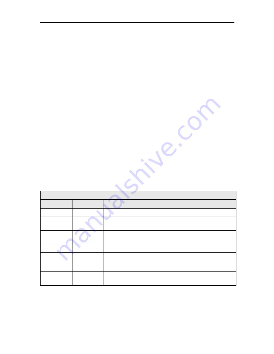
Table 4-2. Switch Status LEDs
LED
Color
Description
Normal
Green
Indicates that the unit is currently under power.
Major Alarm
Red
Indicates that at least one satellite channel did not receive
redundancy protection and is off-line.
Minor Alarm
Yellow
Indicates that a redundancy warning exists and the RCS20 may
not be providing redundancy protection.
Test Mode
Yellow
Indicates that the switch is performing one of the system tests.
Event
Yellow
Indicates that a condition of system event as occurred that the
RCS20 has stored in memory. The events may be viewed from
the Front Panel or from the Terminal port.
Remote
Green
Indicates that the unit is set to respond from either the Terminal
port or the Remote M&C port
4.1.5 Guide to Front Panel Monitor and Control
The front panel can be used to perform complete monitor and configuration of the RCS20. The
operation of the front panel becomes easy after a short period of use in which the user becomes
Summary of Contents for RCS20
Page 2: ......
Page 36: ...Installation RCS20 M N Redundancy Switch 2 24 TM056 Rev 2 3...
Page 47: ...RCS20 M N Redundancy Switch User Interfaces TM056 Rev 2 3 4 9 Figure 4 2...
Page 48: ...User Interfaces RCS20 M N Redundancy Switch 4 10 TM056 Rev 2 3 Figure 4 3...
Page 49: ...RCS20 M N Redundancy Switch User Interfaces TM056 Rev 2 3 4 11 Figure 4 4...
Page 58: ...User Interfaces RCS20 M N Redundancy Switch 4 20 TM056 Rev 2 3...
Page 84: ...Maintenance RCS20 M N Redundancy Switch 6 6 TM056 Rev 2 3...
Page 100: ...Appendix A RCS20 M N Redundancy Switch A 14 TM056 Rev 2 3...
Page 112: ...Appendix B RCS20 M N Redundancy Switch B 12 TM056 Rev 2 3...


