background image

 DMDVB20 LBST Satellite Modem 


Appendix B 

 TM138 – Rev. 1.0


B-1


Front Panel Upgrade Procedure 

B


B.0  Introduction 


The Satellite Modem offers the ability to perform field upgrades of the modem’s feature set 
quickly and easily from the front panel.  Purchased upgrades will become part of the modems 
permanent configuration.  Demonstration upgrades will enable the optional features for a 30-day 
evaluation period. 


B.1  Required Equipment 

 
The Satellite Modem is the only equipment required for this procedure. 


B.2  Upgrade Procedure 

 
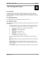
The following paragraphs describe the procedure for permanently updating the feature set of the 
Satellite Modem  
 
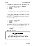
1. 

The following steps allow users to quickly determine from the front panel whether or not 
the desired feature(s) are supported by the hardware currently installed in the modem. 


a. 

From the modem’s Main Menu, scroll right to the SYSTEM Menu. 

b. Scroll 

down. 

c. 

Scroll right to the HW/FW CONFIG Menu. 

d. Scroll 

down 

e. 

Scroll right to the FEATURES Menu.   

f. Scroll 

down. 

g. 

Scroll right to the UPGRADE LIST Menu. 

h. Scroll 

down. 

i. 

Scroll right through the available list of options. 


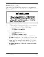
The top line identifies the options and the second line identifies the following options 
status: 


INSTALLED

 indicates that the option is already available as part of the modems feature 

set. 
 

HW & KEY REQ

 indicates that additional hardware is required to support the option.  

Contact your Radyne sales representative for more information regarding the required 
hardware upgrade. 

 
KEY CODE REQ

 indicates that the desired option is available as a front panel upgrade. 


Summary of Contents for DMDVB20 LBST

Page 1: ...L Band Satellite Modulator With DVB S2 Receiver and ODU Driver Installation and Operation Manual TM138 Revision 1 0 Radyne Corporation 3138 E Elwood St Phoenix AZ 85034 602 437 9620 Fax 602 437 4811...

Page 2: ...to shipping storage accident abuse alteration misuse neglect failure to use products under normal operating conditions failure to use products according to any operating instructions provided by Rady...

Page 3: ...be accomplished The Repair Authorization may be requested in writing or by calling Radyne Corp 3138 E Elwood St Phoenix Arizona 85034 USA ATTN Customer Support Phone 602 437 9620 Fax 602 437 4811 Any...

Page 4: ...closed in less than and greater than brackets For example the Reset Alarms Pushbutton will be shown as RESET ALARMS while a command that calls for the entry of a 7 followed by ENTER Key will be repres...

Page 5: ...or related documents are believed reliable but the accuracy and completeness thereof are not guaranteed or warranted and they are not intended to be nor should they be understood to be representation...

Page 6: ...ator Checkout ______________________________________________________ 2 5 2 5 1 Initial Power Up________________________________________________________ 2 5 2 5 2 Factory Terminal Setup________________...

Page 7: ...ving __________________________________________________________ 3 13 3 8 Locating the ID Code Operational Procedure__________________________________ 3 15 3 9 Strap Codes TX Only Option ______________...

Page 8: ..._______ 5 2 5 3 5 EXT CLK J16 ________________________________________________________ 5 3 5 3 6 ASYNC J17 NOT SUPPORTED _________________________________________ 5 3 5 3 7 J18 _______________________...

Page 9: ..._______________________ 7 4 7 8 2 DVB_________________________________________________________________ 7 5 7 9 DMDVB20 LBST Demodulator Specifications __________________________________ 7 7 7 9 Data R...

Page 10: ...1 C 3 Carrier Auto ____________________________________________________________ C 1 C 4 Carrier VSat____________________________________________________________ C 1 C 5 Carrier RTS __________________...

Page 11: ...Table of Contents DMDVB20 LBST Satellite Modem xii TM138 Rev 1 0...

Page 12: ...terface type can be readily set and changed at the Front Panel by earth station operations personnel The modulator operates at all standard IBS Data Rates up to 8 448 Mbps Selection of any data rate i...

Page 13: ...ures are done remotely or through the front panel of the modem Features may be purchased at any time by contacting a Radyne Corp salesperson Refer to Section 4 and Appendix D for information on how up...

Page 14: ...DMDVB20 LBST Satellite Modem Introduction TM138 Rev 1 0 1 3...

Page 15: ...T The rear panel of the modem is has power entering from the left and IF Cabling entering from the right as viewed from the rear of the unit Data and Control Cabling can enter from either side PROPER...

Page 16: ...em was carefully packaged to avoid damage and should arrive complete with the following items for proper installation Modem Unit Power Cord with applicable AC Connector Installation and Operation Manu...

Page 17: ...l integrity and proper receive operation Do not mount the in an unprotected outdoor location where there is direct contact with rain snow wind or sun The only tools required for rack mounting are four...

Page 18: ...dBm Demodulator Data Rate 2 048 Mbps Mode DVB S2 Frequency 1200 MHz Modulation QPSK Inner FEC 1 2 Rate S2 Satellite Framing DVB S2 Normal Terrestrial Framing None Pilot Symbols Disabled Usage of the m...

Page 19: ...sor will test itself and several of its components before beginning its Main Monitor Control Program These power up diagnostics show no results if successful If a failure is detected the Fault LED wil...

Page 20: ...Installation DMDVB20 LBST Satellite Modem 2 6 TM138 Rev 1 0...

Page 21: ...ed circuit card refer to Appendix A A block diagram of the Modem is shown in Figure 3 1 Figure 3 1 Block Diagram 3 0 1 L Band Printed Circuit Card The L Band circuit cards consists of an analog modula...

Page 22: ...nly be implemented in dedicated integrated circuits are now downloaded from a micro controller through a serial or peripheral interface When a new digital logic function is needed a new configuration...

Page 23: ...are used to interconnect the M C to all components of the modem Communication to the outside world is done via connections to the remote port terminal port Ethernet port and alarm ports The M C runs o...

Page 24: ...g The Baseband Processor performs all Modulator functions required for an IBS Framing Unit and Reed Solomon Codec In addition the Baseband Processing Section provides for transmit clock selection and...

Page 25: ...to most of the circuitry on any board contained in the modem These connections provide status on the working condition of the circuitry as well as providing the data required for the various measurem...

Page 26: ...Protocol Equipment Remote Mode setup can be entered from the front panel under the System menu This requires the user to first set the Remote Port Control to Remote then set the Multidrop Address as...

Page 27: ...ts that appear at Pins 18 21 on J19 Mod Fault Will sink up to 20 ma maximum until a transmit or common fault is detected Will not sink current if a fault is detected Demod Fault Will sink up to 20 ma...

Page 28: ...unit RX Terrestrial Loopback Receive Data from the satellite is looped back for retransmission to the satellite providing a far end loopback prior to the framing unit RX Baseband Loopback Receive Data...

Page 29: ...DMDVB20 LBST Satellite Modem Theory of Operation TM138 Rev 1 0 3 9 Figure 3 5 Loopback Functional Block Diagram...

Page 30: ...sses the various clocks for the Tx Clock source and the Rx Buffer Clock source Tx and Rx Clocks may be independently locked Figure 3 6 Clocking and Polarity Diagram 3 5 1 TX Clock Options TX clock opt...

Page 31: ...ferred to as SCR SCR is also referred to as Receive Clock Satellite Clock or Receive Timing RT When SCT clock is configured as Internal the frequency of the clock is set the same as the Transmit Terre...

Page 32: ...distant end If selected the Buffer Clock is lock to the RX sat clock 3 5 3 EXT REF External Reference Top BNC Port J10 This is not actually a clock but does have some clocking implications When the ex...

Page 33: ...Receiving Modem it is fed to a Viterbi Decoder for the first layer of error correction After error correction is performed by the Viterbi Decoder the unique words are located and the data is deinterl...

Page 34: ...128 256 384 512 768 1024 1536 126 112 7 126 112 7 126 112 7 126 112 7 126 112 7 126 112 7 126 112 7 126 112 7 0 125 0 125 0 125 0 125 0 125 0 125 0 125 0 125 4 4 4 4 4 4 4 4 115 58 29 19 15 10 8 5 ID...

Page 35: ...hat is required to be entered in the ID code field Once the new ID code is entered the modem will activate the new features Refer to Appendix B for upgrade procedures 3 9 Strap Codes TX Only Option Th...

Page 36: ...Theory of Operation DMDVB20 LBST Satellite Modem 3 16 TM138 Rev 1 0...

Page 37: ...fer to the Section 4 6 4 1 Front Panel User Interface The Front Panel of the DMDVB20 LBST allows for complete control and monitor of all DMDVB20 LBST parameters and functions via a keypad LCD display...

Page 38: ...ate The lower line shows the current value of that parameter The LCD display is a single entry window into the large matrix of parameters that can be monitored and set from the Front Panel 4 1 2 Curso...

Page 39: ...ower Green Indicates that the unit is turned on Fault Red Indicates a hardware fault for the unit Event Yellow Indicates that a condition or event has occurred that the modem has stored in memory The...

Page 40: ...press ENTER to lock in the new parameter If a change needs to be made prior to pressing ENTER depress CLEAR and the display defaults back to the original parameter Depress ENTER again and re enter the...

Page 41: ...of operation DVB Per EN301 421 En301 210 Data Rates All Rates Framing Type DVB Scrambler Type DVB Spectrum Mask DVB 0 25 0 35 Closed Net All possible combinations allowed however a DVB setting requir...

Page 42: ...required if the BUC LO is higher in frequency than the BUC output frequency When BUC LO is higher than the BUC output frequency this creates a spectral inversion and the IF Spectrum must be again inve...

Page 43: ...hen using DVB Network Specifications DATA POLARITY INV TERR BASE INV BASEBAND INV TERR DATA NONE Allows the user to invert the Tx Data polarity REED SOLOMON menu These selections are visible only when...

Page 44: ...he incorrect manufacturers BUC the unit will display a fault BUC OUTPUT Enable Disable Only available when the FSK Comm is Enabled Enables or Disables the BUC RF Output LO FREQ MHz Allows the user to...

Page 45: ...cations between the modem and BUC Only available when the FSK Comm is Enabled BUC OUTPUT Enable Disable Only available when the FSK Comm is Enabled Enables or Disables the BUC RF Output FSK TEST NONE...

Page 46: ...IF Frequency in 1 Hz increments DWNLNK FREQ MHz Displays the input frequency into the LNB from the satellite also referred known as Satellite downlink frequency The user must enter the LNB LO and OSC...

Page 47: ...or Data Rates Allows the user to set the Data Rate in bps steps via the Front Panel Arrows or Keypad SYMB RATE sps Allows the user to view the Symbol Rate Maximum SR is 10 MSps INNER FEC DVB S2 Normal...

Page 48: ...nter HIGH SIDEBAND 10 MHz LNB REF ENABLED DISABLED Allows the user to enable or disable the 10 MHz BUC reference clock VOLTAGE SELECT 13 15 18 20 Allows the user to select the voltage required by the...

Page 49: ...nu has three fields the first field is the name of the clock source the second field is the priority entry area and the last field is the depth of the list In the priority field the up down arrow keys...

Page 50: ...ows the user to select rear panel contact closures to support IBS Minor and Major alarms 4 3 5 Monitor Menu Options and Parameters EVENTS Displays a history of events recorded in the event buffer A ma...

Page 51: ...r bus located inside the modem 12V SUPPLY Displays the measured voltage of the 12 Volt power bus located inside the modem BUC CURRENT Displays the measured current of the BUC BUC VOLTAGE Displays the...

Page 52: ...modem SYM CLOCK PLL Pass Fail Unmasked Masked Indicates that the Tx Symbol Clock PLL is not locked This alarm will flash on during certain modem parameter changes A solid indication points toward a p...

Page 53: ...ING TX CLK SRC FALLBK Pass Fail Unmasked Masked Indicates that the clock resource has fallen BUC PLL Pass Fail Unmasked Masked Indicates that the BUC has a PLL fault Only available when used with Smar...

Page 54: ...llows user to enable a forced Rx summary alarm RX MINOR menu BUFF UNDERFLOW Pass Fail Unmasked Masked Indicates that a Doppler Buffer underflow has occurred BUFF NEAR EMPTY Pass Fail Unmasked Masked I...

Page 55: ...ted inside the modem 1 5V TX SUPPLY Pass Fail Unmasked Masked Displays the measured voltage of the 1 5 Volt Tx power bus located inside the modem 3 3V SUPPLY Pass Fail Unmasked Masked Displays the mea...

Page 56: ...ntermittent failures TX MAJOR menu FPGA CFG DSP CFG SCT CLOCK PLL SYM CLOCK PLL LB SYNTH PLL BUC CURRENT BUC VOLTAGE TX MINOR menu TERR CLK ACT TERR DATA ACT TX TERR AIS DnI FRAME LOCK DnI M FRAME LOC...

Page 57: ...EMPTY BUFF NEAR FULL BUFF OVERFLOW RX DATA ACTIVITY EBNO COMMON menu TERR FPGA CFG CODEC FPGA CFG CODEC DEV CFG EXT CLOCK ACT EXT REF ACT EXT REF LOCK VOLTAGE menu 1 5V RX SUPPLY 1 5V TX SUPPLY 3 3V S...

Page 58: ...ff 00 no timeout KEY CLICK ON OFF Allows the user to enable or disable the audible beep each time a key is pressed Illegal entries will still cause a beep to be heard MENU NAVIGATION STANDARD FLOATING...

Page 59: ...00 hex Modem IP Address 010 000 000 001 C0 A8 00 EE hex Server IP Address 010 001 001 001 0A 01 01 01 hex Router IP Address 010 000 001 001 0A 00 01 01 hex BOOTP During initialization boot up the mode...

Page 60: ...then the address should be set to a foreign address This address is expressed in hexadecimal format BOOTP SERVER XXX XXX XXX XXX Hexadecimal Address ddd ddd ddd ddd Decimal Address The IP Address of...

Page 61: ...ser to adjust the internal frequency reference for calibration Only displayed of the system reference clock is INTERNAL HI STAB VCO ADJUST 0 100 Allows the user to adjust the internal frequency refere...

Page 62: ...only FRONT PANEL BOARD Indicates the Radyne assembly number for the front panel board FEATURES menu 5012 2840 2417 ____ ____ ____ Allows the user to install purchased feature upgrades see Appendix A...

Page 63: ...CK WITH ETHERNET DATA INTERFACE Usage of the modems loopback capabilities in conjunction with the Ethernet data interface can produce undesirable network loops In order to run any type of data test wi...

Page 64: ...User Interfaces DMDVB20 LBST Satellite Modem 4 28 TM138 Rev 1 0 OFFSET Causes a single sideband output POS FIR For manufacturer s use only NEG FIR For manufacturer s use only...

Page 65: ...re supported VT 100 WYSE 50 and ADDS VP is used for setting the screen when the terminal is used for the first time the non volatile memory is reset 4 4 2 Modem Setup for Terminal Mode Terminal Mode C...

Page 66: ...ENTER If the parameter to be changed requires a numeric value enter the number followed by ENTER If the parameter is non numeric press SPACE to cycle through the list of available entries Items that...

Page 67: ...DMDVB20 LBST Satellite Modem User Interfaces TM138 Rev 1 0 4 31...

Page 68: ...ors located on the rear of the unit refer to Figure 5 1 for the DMDVB20 LBST The connector definitions below are those on the DMDVB20 LBST unit Any connection interfacing to the DMDVB20 LBST must be t...

Page 69: ...able 5 1 for pinouts Table 5 1 DC Power A B Ground C 5 3 DMDVB20 LBST Chassis Connections 5 3 1 EXT REF J10 The External Reference Port is a 50 Ohm Female BNC Connector and will accept the following f...

Page 70: ...Major Alarm Status on the Modulator and Demodulator When the modem is configured for IBS Network Specification pins 7 9 only support the IBS Prompt Alarms and pins 10 12 only support IBS Service Alarm...

Page 71: ...nd A CS A Output 6 Data Mode A DM A Output 7 Signal Ground SGND 8 Receiver Ready A RR A Output 9 Receive Timing B RT B Output 10 Receiver Ready B RR B Output 11 Terminal Timing B TT B Input 12 Send Ti...

Page 72: ...3 Receive Data RS 232 RXD 232 Input 4 NC NC 5 Ground GND 6 Transmit Data RS 485 TX 485 A Output 7 NC No Connection 8 Receive Data RS 485 RX 485 B CTS Input 9 Receive Data RS 485 RX 485 A Input When op...

Page 73: ...Rear Panel Interfaces DMDVB20 LBST Satellite Modem 5 6 TM138 Rev 1 0...

Page 74: ...ssembly inside the case and replacement is not intended in the field 6 0 1 Clock Adjustment The modem allows for VCO speed adjustment from the front panel Clock adjustment should be performed only whe...

Page 75: ...re DSP CFG Indicates a transmit FPGA failure SCT Clock PLL Indicates that the Tx SCT Clock PLL is not locked This alarm will flash on during certain modem parameter changes A solid indication points t...

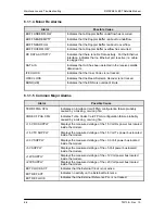
Page 76: ...ndication points toward a configuration problem within the modem 6 1 1 3 Minor Tx Alarms Alarm Possible Cause TERR CLK ACT Indicates no Terrestrial Clock activity TERR DATA ACT Indicates no Tx Data ac...

Page 77: ...Common Major Alarms Alarm Possible Cause TERR FPGA CFG Indicates an Interface Card FPGA configuration failure probably caused by a missing or wrong file CODEC FPGA CFG Indicates Turbo Codec Card FPGA...

Page 78: ...ay illuminated Alarms are grouped into Transmit and Receive Alarms Transmit and Receive are completely independent 6 2 1 2 Minor Alarms Minor Alarms indicate that a problem may persist outside the mod...

Page 79: ...Maintenance and Troubleshooting DMDVB20 LBST Satellite Modem 6 6 TM138 Rev 1 0...

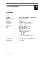
Page 80: ...Temperature Output Spectrum Meets IESS 309 310 Power Spectral Mask Spurious 50 dBc In Band 45 dBc Out of Band On Off Power Ratio 60 dB Scrambler CCITT V 35 or IBS Others Optional FEC Viterbi 1 2 3 4 a...

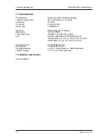
Page 81: ...inimum Spectrum ETSI EN302 307 Compliant Input Level 60 TO 20DbM Total Input Power 20 dBm or 40 dBc the Lesser FEC DVB S2 LDPC BCH Per ETSI EN 302 307 Normal Block 1 2 3 5 2 3 3 4 4 5 5 6 8 9 9 10 Sho...

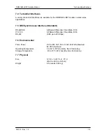
Page 82: ...Standard RS 422 530 All Rates Differential Clock Data DCE ITU V 35 All Rates Differential Clock Data DCE RS 232 DCE up to 200 Kbps 7 6 Environmental Prime Power 100 to 240 VAC 50 to 60 Hz 40 Watts Ma...

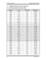
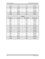
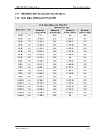
Page 83: ...2400 4772727 BPSK TPC 3 4 4100 6990000 BPSK TPC 7 8 4200 8200000 QPSK NONE 9600 20000000 QPSK VIT 1 2 4800 10000000 QPSK VIT 3 4 7200 15000000 QPSK VIT 7 8 8400 17500000 QPSK SEQ 1 2 4800 2048000 QPS...

Page 84: ...00 6875000 BPSK VIT 5 6 3667 7638888 BPSK VIT 7 8 3850 8020833 QPSK VIT 1 2 4400 9166666 QPSK VIT 2 3 5867 12222222 QPSK VIT 3 4 6600 13750000 QPSK VIT 5 6 7334 15277777 QPSK VIT 7 8 7700 16041666 8PS...

Page 85: ...0 204 Mode Modulation Code Rate Min Data Rate Max Data Rate BPSK VIT 1 2 2400 5000000 BPSK VIT 2 3 3200 6666666 BPSK VIT 3 4 3600 7500000 BPSK VIT 5 6 4000 8333333 BPSK VIT 7 8 4200 8750000 QPSK VIT 1...

Page 86: ...2 376608 20 0 2 313065 20 0 QPSK 4 5 3 174394 20 0 3 016361 20 0 QPSK 5 6 3 309326 20 0 3 192186 20 0 QPSK 8 9 3 532902 20 0 3 455922 20 0 QPSK 9 10 3 577224 20 0 NA NA 8PSK 3 5 3 559982 20 0 3 450638...

Page 87: ...5 2 3 3 4 4 5 5 6 8 9 9 10 1 00 x 10 06 20 MSPS 2 0 2 5 2 7 3 0 3 5 3 8 4 5 4 7 1 00 x 10 06 20 MSPS 2 0 2 5 2 7 3 0 3 5 3 8 4 5 4 7 8PSK DVB S2 BER 3 5 2 3 3 4 5 6 8 9 9 10 1 00 x 10 06 20 MSPS 4 3...

Page 88: ...DMDVB20 LBST Satellite Modem Technical Specifications TM138 Rev 1 0 7 9...

Page 89: ...h an optional TPC Codec Card This card allows variable Reed Solomon rates as well as Turbo Codec and Sequential Codec Outer Code This option must be installed at the factory and may require other opti...

Page 90: ...Appendix A DMDVB20 LBST Satellite Modem A 2 TM138 Rev 1 0...

Page 91: ...determine from the front panel whether or not the desired feature s are supported by the hardware currently installed in the modem a From the modem s Main Menu scroll right to the SYSTEM Menu b Scrol...

Page 92: ...this code from the front panel perform the following a From the modem s Main Menu scroll right to the SYSTEM Menu b Scroll down c Scroll right to the HW FW CONFIG Menu d Scroll down e Scroll right to...

Page 93: ...instructions outlined in the section on Canceling Demonstration Mode 1 The following steps allow users to quickly determine from the front panel whether or not the desired feature s are supported by t...

Page 94: ...iginally requested To enter this code from the front panel perform the following a From the modem s Main Menu scroll right to the SYSTEM Menu b Scroll down c Scroll right to the HW FW CONFIG Menu d Sc...

Page 95: ...follows 1 From the FEATURES Menu 2 Scroll down 3 Scroll right to the UPGRADE LIST Menu 4 Scroll down 5 Scroll right through the available list of options The top line identifies the options and the s...

Page 96: ...l down 3 Scroll right to the HW FW CONFIG Menu 4 Scroll down 5 Scroll right to the FEATURES Menu 6 Scroll down The value displayed on the top line of this menu is the 12 digit Unit ID It is displayed...

Page 97: ...DMDVB20 LBST Satellite Modem Appendix B TM138 Rev 1 0 B 7...

Page 98: ...ctions that may alter the output spectrum and the user is required to manually turn on the output after the reprogramming C 3 Carrier Auto Modulator output is turned off before reprogramming modulator...

Page 99: ...When using the terminal the modulator is turned off while re programming modulator functions that may alter the output spectrum and the user is required to manually turn on the output after the repro...

Page 100: ...DMDVB20 LBST Satellite Modem Appendix C TM138 Rev 1 0 C 3...

Page 101: ...de Table D 1 for available strap codes Table D 1 Strap Codes Dis Disable Strap Code Decimal Data Rate Kbps Overhead Code Rate Type Framing Type Scrambler Type Reed Solomon Modulation Mode 1 64 16 15 1...

Page 102: ...S Dis QPSK CNT 14 1536 1 3 4 VIT NONE V 35 IESS Dis QPSK CNT 19 1544 1 1 2 VIT NONE V 35 IESS Dis QPSK CNT 21 1544 1 3 4 VIT NONE V 35 IESS Dis QPSK CNT 22 1920 1 1 2 VIT NONE V 35 IESS Dis QPSK CNT 2...

Page 103: ...IBS IBS Dis QPSK CNT 168 768 16 15 3 4 VIT IBS IBS Dis QPSK IBS 193 832 16 15 1 2 VIT IBS IBS Dis QPSK CNT 194 832 16 15 3 4 VIT IBS IBS Dis QPSK CNT 196 896 16 15 1 2 VIT IBS IBS Dis QPSK CNT 208 89...

Page 104: ...S Dis QPSK IBS 135 1984 16 15 1 2 VIT IBS IBS Dis QPSK CNT 139 1984 16 15 3 4 VIT IBS IBS Dis QPSK CNT 45 3088 1 1 2 VIT NONE V 35 IESS Dis QPSK CNT 141 3088 1 3 4 VIT NONE V 35 IESS Dis QPSK CNT 176...

Page 105: ...ny mode of operation can be entered from this starting point Case 1 IBS 1 544 Mbps 3 4 Rate Viterbi Starting with the Data Rate 512 Kbps Modulator Method 1 Under Interface Menu Set Interface type Set...

Page 106: ...ate Viterbi IBS Overhead Starting with the Data Rate 512 Kbps Modulator Method 1 Under Interface Menu Set Interface type Set Tx clock selection Under Mod Data Menu Set code rate to 3 4 VIT Set Framing...

Page 107: ...DMDVB20 LBST Satellite Modem Appendix D TM138 Rev 1 0 D 7...

Page 108: ...inary 1s AMSL Above Mean Sea Level ANSI American National Standards Institute ASCII American Standard Code for Information Interchange ASIC Application Specific Integrated Circuit ATE Automatic Test E...

Page 109: ...Noise Ratio D DAC Digital to Analog Converter dB Decibels dBc Decibels Referred to Carrier dBm Decibels Referred to 1 0 milliwatt DC Direct Current Demod Demodulator or Demodulated DPLL Digital Phase...

Page 110: ...Firmware G g Force of Gravity GHz Gigahertz GND Ground H HSSI High Speed Serial Interface HW Hardware Hz Hertz Unit of Frequency I IBS Intelsat Business Services IDR Intermediate Data Rate I O Input O...

Page 111: ...MFAS Multi Frame Acquisition Sync See FAS MHz Megahertz MIB Management Information Base Mod Modulator or Modulated ms or msec Millisecond M C Monitor and Control N NC Normally Closed NO Normally Open...

Page 112: ...ased error correcting codes with a wide range of applications in digital communications and storage S SCC Satellite Control Channel A Radyne satellite format SEQ Sequential SYNC Synchronize T TBD To B...

Page 113: ...Glossary DMDVB20 LBST Satellite Modem G 6 TM138 Rev 1 0 W X Y Z W Watt Misc s Microsecond 16QAM 16 Quadrature Amplitude Modulation 8PSK 8 Phase Shift Keying...

Reviews: