Theory of Operation
DMDVB20 LBST Satellite Modem
3-6
TM138 – Rev. 1.0
3.2.1 Terminal Port (Supported in Rev B or greater)
This port supports an asynchronous control protocol as described in Section 4. It is configured to
support RS-232 signal levels. This port is intended for use in computer-based remote M&C. All
functions of the modem may be monitored and controlled from this port via a common terminal
connected to the Terminal Port. This function is front panel selectable.
The Terminal Mode Control allows the use of an external terminal or computer to monitor and
control the modem from a full screen interactive presentation operated by the modem itself. No
external software is required other than VT-100 Terminal Emulation Software (e.g. “Procomm”
for a computer when used as a terminal. The Control Port is normally used as an RS–232
Connection to the terminal device. The RS-232 operating parameters can be set using the
modem Front Panel and stored in Non-volatile memory for future use.
Refer to the Remote Protocol Manual (TM137) for the Terminal and
Remote screens and protocols.
3.2.2 Modem Remote Communications (RLLP)
The Remote Port located on J20 allows for control and monitoring of parameters and functions
via an RS-232 Serial Interface, or RS-485 for RLLP Protocol. ‘Equipment Remote Mode’ setup
can be entered from the front panel under the “System” menu. This requires the user to first set
the Remote Port Control to “Remote” then set the Multidrop Address as needed followed by
setting the Remote Interface to RS232 or RS485.
Control and status messages are conveyed between the modem and all subsidiary modems and
the host computer using packetized message blocks in accordance with a proprietary
communications specification. This communication is handled by the Radyne Link Level Protocol
(RLLP), which serves as a protocol ‘wrapper’ for the RM&C data. Complete information on
monitor and control software is contained in the following sections.
3.2.3 Ethernet M&C Port (Not Supported)
3.2.4 Modem Monitor Status
The modems M&C system is connected to most of the circuitry on any board contained in the
chassis. These connections provide status on the working condition of the circuitry as well as
providing the data required for the various measurements the modem provides. The M&C
processes this information and generates status indications as well as alarms when necessary.
Detailed status information is available via the modems various user interfaces (front panel,
remote and terminal). A summary of this information can be connected to external equipment,
switches or alarms via the open collector and/or form-C fault connections
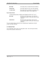
Form-C Contacts:
The UIM provides three Form-C Relays under processor control that appear at J15.
Summary of Contents for DMDVB20 LBST
Page 11: ...Table of Contents DMDVB20 LBST Satellite Modem xii TM138 Rev 1 0...
Page 14: ...DMDVB20 LBST Satellite Modem Introduction TM138 Rev 1 0 1 3...
Page 20: ...Installation DMDVB20 LBST Satellite Modem 2 6 TM138 Rev 1 0...
Page 36: ...Theory of Operation DMDVB20 LBST Satellite Modem 3 16 TM138 Rev 1 0...
Page 67: ...DMDVB20 LBST Satellite Modem User Interfaces TM138 Rev 1 0 4 31...
Page 73: ...Rear Panel Interfaces DMDVB20 LBST Satellite Modem 5 6 TM138 Rev 1 0...
Page 79: ...Maintenance and Troubleshooting DMDVB20 LBST Satellite Modem 6 6 TM138 Rev 1 0...
Page 88: ...DMDVB20 LBST Satellite Modem Technical Specifications TM138 Rev 1 0 7 9...
Page 90: ...Appendix A DMDVB20 LBST Satellite Modem A 2 TM138 Rev 1 0...
Page 97: ...DMDVB20 LBST Satellite Modem Appendix B TM138 Rev 1 0 B 7...
Page 100: ...DMDVB20 LBST Satellite Modem Appendix C TM138 Rev 1 0 C 3...
Page 107: ...DMDVB20 LBST Satellite Modem Appendix D TM138 Rev 1 0 D 7...

