DMDVB20 LBST Satellite Modem
Introduction
TM138 – Rev. 1.0
1-1
Introduction
1
This chapter provides an overview of the DMDVB20 LBST Satellite Modem. The DMDVB20
LBST will be referred to in this manual as “the standard unit” and the DMDVB20 LBST will be
referred to as the LBST. When describing the DMDVB20 LBST, it may be referred to as “the
DMDVB20 LBST”, “the modem”, or “the unit”.
1.0 Overview
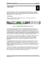
The Radyne DMDVB20 LBST Satellite Modem (Figure 1-1) offers the best features of a
sophisticated programmable modem.
Figure 1-1. DMDVB20 LBST Satellite Modem Front Panel
This versatile equipment package combines unsurpassed performance with numerous user-
friendly Front Panel Programmable Functions. The DMDVB20 LBST provides different services
for the modulator and the demodulator. The modulator supported services are: Closed net,
Intelsat IBS and DVB -S. The demodulator support DVB-S2. All of the configuration and Monitor
and Control (M&C) Functions are available at the Front Panel. Operating parameters, such as
variable data rates, FEC Code Rate, modulation type, IF Frequencies, Framing and interface type
can be readily set and changed at the Front Panel by earth station operations personnel.
The modulator operates at all standard IBS Data Rates up to 8.448 Mbps. Selection of any data
rate is provided over the range of 2.4 Kbps to 20 Mbps in 1 bps steps. The Demodulator
supports DVB-S2 Broadcast Services. The DVB-S2 supports QPSK, 8PSK and 16APSK
applications with symbol rates of 2 to 20 Msps. Standard Interface available on the unit is
RS422/530.
The DMDVB20 LBST offers additional features that serves as an interface between the indoor
unit (DMDVB20 LBST) and the outdoor units (consisting of the BUC and LNB). The output
frequency of the LBST is 950 to 2050 MHz. The LBST TX port can supply voltage, 10 MHz
Reference and FSK to the BUC via the IFL cable. The RX port can supply LNB via the IFL Cable.
The BUC voltage supplied to the BUC can either be 24 or 48 Volts. The Rx Port LNB voltage
consists of 18 volts.
The LBST has the capability to enable and disable the BUC/LNB voltages and 10 MHz reference
via the front panel. In addition, monitoring features provide verification of system status. The
LBST monitors both the current and the voltage at the output of the Tx Port, thus allowing the
user to monitor the status of both the indoor units and outdoor units.
Summary of Contents for DMDVB20 LBST
Page 11: ...Table of Contents DMDVB20 LBST Satellite Modem xii TM138 Rev 1 0...
Page 14: ...DMDVB20 LBST Satellite Modem Introduction TM138 Rev 1 0 1 3...
Page 20: ...Installation DMDVB20 LBST Satellite Modem 2 6 TM138 Rev 1 0...
Page 36: ...Theory of Operation DMDVB20 LBST Satellite Modem 3 16 TM138 Rev 1 0...
Page 67: ...DMDVB20 LBST Satellite Modem User Interfaces TM138 Rev 1 0 4 31...
Page 73: ...Rear Panel Interfaces DMDVB20 LBST Satellite Modem 5 6 TM138 Rev 1 0...
Page 79: ...Maintenance and Troubleshooting DMDVB20 LBST Satellite Modem 6 6 TM138 Rev 1 0...
Page 88: ...DMDVB20 LBST Satellite Modem Technical Specifications TM138 Rev 1 0 7 9...
Page 90: ...Appendix A DMDVB20 LBST Satellite Modem A 2 TM138 Rev 1 0...
Page 97: ...DMDVB20 LBST Satellite Modem Appendix B TM138 Rev 1 0 B 7...
Page 100: ...DMDVB20 LBST Satellite Modem Appendix C TM138 Rev 1 0 C 3...
Page 107: ...DMDVB20 LBST Satellite Modem Appendix D TM138 Rev 1 0 D 7...


