


DMD50 Universal Satellite Modem
User Interfaces
TM118 – Rev. 1.1
4-43
Control and status messages are conveyed between the modem and all subsidiary modems and
the host computer using packetized message blocks in accordance with a proprietary
communications specification. This communication is handled by the Radyne Link Level Protocol
(RLLP), which serves as a protocol ‘wrapper’ for the RM&C data. Complete information on
monitor and control software is contained in the following sections.
4.8.1 Protocol Structure
The Communications Specification (COMMSPEC) defines the interaction of computer resident
Monitor and Control Software used in satellite earth station equipment such as modems,
redundancy switches, multiplexers, and other ancillary support gear. Communication is bi-
directional, and is normally established on one or more full-duplex 9600-baud multi-drop control
buses that conform to EIA Standard RS-485.
Each piece of earth station equipment on a control bus has a unique physical address, which is
assigned during station setup/configuration or prior to shipment. Valid decimal addresses on one
control bus range from 032 through 255 supporting up to 224 devices per bus. Address 255 of
each control bus is usually reserved for the M&C computer.
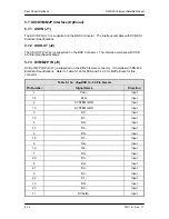
4.9 Ethernet Remote Port Interface (SNMP & Web Browser)
This port is dedicated for Ethernet Communications supporting SNMP, FTP and Web Browser.
The port is configured for 10 Base-T communications protocols. The Ethernet M&C Interface
requires a standard RJ45 Male connector.
Refer to Appendix D and F for proper setup of the TCP-IP interface and Web Browser
Setup.
Refer to the Remote Protocol Manual TM-117 for SNMP MIB and Web Browser Menus
Summary of Contents for DMD50
Page 2: ......
Page 3: ......
Page 16: ...DMD50 Universal Satellite Modem Table of Contents TM118 Rev 1 1 xv...
Page 17: ......
Page 20: ...DMD50 Universal Satellite Modem Introduction TM118 Rev 1 1 1 3...
Page 21: ......
Page 27: ...Installation DMD50 Universal Satellite Modem 2 6 TM118 Rev 1 1...
Page 53: ...Theory of Operation DMD50 Universal Satellite Modem 3 26 TM118 Rev 1 1...
Page 97: ...User Interfaces DMD50 Universal Satellite Modem 4 44 TM118 Rev 1 1...
Page 122: ...DMD50 Universal Satellite Modem Rear Panel Interfaces TM118 Rev 1 1 5 25...
Page 123: ......
Page 132: ...DMD50 Universal Satellite Modem Maintenance and Troubleshooting TM118 Rev 1 1 6 9...
Page 133: ......
Page 158: ...DMD50 Universal Satellite Modem Technical Specifications TM118 Rev 1 1 7 25...
Page 159: ......
Page 162: ...DMD50 Universal Satellite Modem Appendix A TM118 Rev 1 1 A 3...
Page 163: ......
Page 170: ...DMD50 Universal Satellite Modem Appendix B TM118 Rev 1 1 B 7...
Page 171: ......
Page 174: ...DMD50 Universal Satellite Modem Appendix C TM118 Rev 1 1 C 3...
Page 175: ......
Page 184: ...DMD50 Universal Satellite Modem Appendix D TM118 Rev 1 1 D 9...
Page 185: ......
Page 192: ...DMD50 Universal Satellite Modem Appendix E TM118 Rev 1 1 E 7...
Page 193: ......
Page 200: ...DMD50 Universal Satellite Modem Appendix F TM118 Rev 1 1 F 7...
Page 201: ......
Page 205: ...Appendix G DMD50 Universal Satellite Modem G 4 TM118 Rev 1 1...
Page 224: ...DMD50 Universal Satellite Modem Appendix H TM118 Rev 1 1 H 19...
Page 225: ......
Page 231: ...Appendix I DMD50 Universal Satellite Modem I 6 TM118 Rev 1 1...


