


DMD50 Universal Satellite Modem
User Interfaces
TM118 – Rev. 1.1
4-27
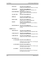
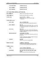
+5V SUPPLY
{Pass/Fail, Unmasked/Masked}
Displays the measured voltage of the +5 Volt power bus
located inside the modem.
+12V SUPPLY
{Pass/Fail, Unmasked/Masked}
Displays the measured voltage of the +12 Volt power
bus located inside the modem.
+20V SUPPLY
{Pass/Fail, Unmasked/Masked}
Displays the measured voltage of the +20 Volt power
bus located inside the modem.
-12V SUPPLY
{Pass/Fail, Unmasked/Masked}
Displays the measured voltage of the -20 Volt power bus
located inside the modem.
EXT CLOCK ACT
{Pass/Fail, Unmasked/Masked}
Indicates the External Clock activity.
EXT REF ACT
{Pass/Fail, Unmasked/Masked}
Indicates the External Reference activity.
EXT REF LOCK
{Pass/Fail, Unmasked/Masked}
Indicates the External Reference PLL is locked
detection.
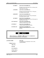
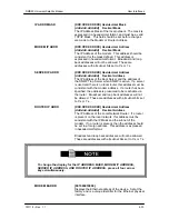
Refer to Section 4.3.7, “CURRENT ALARMS (menu)” for an explanation of
the Latched Alarms Menu Options and Parameters.
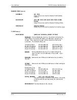
LATCHED ALARMS
{Pass/Fail}
The following alarms are latched in order to catch
intermittent failures:
TX MAJOR (menu)
FPGA CFG
DSP CFG
SCT CLOCK PLL
SYM CLOCK PLL
LB SYNTH PLL
Summary of Contents for DMD50
Page 2: ......
Page 3: ......
Page 16: ...DMD50 Universal Satellite Modem Table of Contents TM118 Rev 1 1 xv...
Page 17: ......
Page 20: ...DMD50 Universal Satellite Modem Introduction TM118 Rev 1 1 1 3...
Page 21: ......
Page 27: ...Installation DMD50 Universal Satellite Modem 2 6 TM118 Rev 1 1...
Page 53: ...Theory of Operation DMD50 Universal Satellite Modem 3 26 TM118 Rev 1 1...
Page 97: ...User Interfaces DMD50 Universal Satellite Modem 4 44 TM118 Rev 1 1...
Page 122: ...DMD50 Universal Satellite Modem Rear Panel Interfaces TM118 Rev 1 1 5 25...
Page 123: ......
Page 132: ...DMD50 Universal Satellite Modem Maintenance and Troubleshooting TM118 Rev 1 1 6 9...
Page 133: ......
Page 158: ...DMD50 Universal Satellite Modem Technical Specifications TM118 Rev 1 1 7 25...
Page 159: ......
Page 162: ...DMD50 Universal Satellite Modem Appendix A TM118 Rev 1 1 A 3...
Page 163: ......
Page 170: ...DMD50 Universal Satellite Modem Appendix B TM118 Rev 1 1 B 7...
Page 171: ......
Page 174: ...DMD50 Universal Satellite Modem Appendix C TM118 Rev 1 1 C 3...
Page 175: ......
Page 184: ...DMD50 Universal Satellite Modem Appendix D TM118 Rev 1 1 D 9...
Page 185: ......
Page 192: ...DMD50 Universal Satellite Modem Appendix E TM118 Rev 1 1 E 7...
Page 193: ......
Page 200: ...DMD50 Universal Satellite Modem Appendix F TM118 Rev 1 1 F 7...
Page 201: ......
Page 205: ...Appendix G DMD50 Universal Satellite Modem G 4 TM118 Rev 1 1...
Page 224: ...DMD50 Universal Satellite Modem Appendix H TM118 Rev 1 1 H 19...
Page 225: ......
Page 231: ...Appendix I DMD50 Universal Satellite Modem I 6 TM118 Rev 1 1...


