DMD50 Universal Satellite Modem
User Interfaces
TM118 – Rev. 1.1
4-9
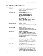
NOMINAL TX POWER
{0 TO -25 dB}
This allows the user to set the nominal Transmit Power.
The nominal transmit power is the default output power
level.
MINIMUM TX POWER
{0 to -25 dB}
This allows the user to set the minimum Transmit Power.
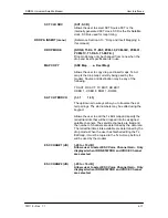
EFDATA
AUPC:
When configured for EFDATA AUPC
the minimum Transmit Power is the lowest power setting
that will be used when the local modem commands a
decrease of the Transmit Power from the Remote
modem.
RADYNE:
When configured for Radyne AUPC, the
minimum Transmit Power is the lowest power setting
that will be used when the remote modem commands a
decrease of the Transmit Power from the Local modem.
NEARSIDE:
When configured for NEARSIDE AUPC the
minimum Transmit Power is the lowest power setting
that will be used by the local modem when the Eb/No
increases above the Eb/No target.
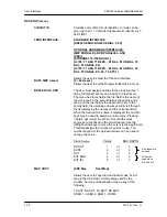
MAXIMUM TX POWER
{0 to -25 dB}
This allows the user to set the maximum Transmit
Power.
EF
AUPC:
When configured for EF AUPC, the
maximum Transmit Power is the highest power setting
that the local modem will use when the local modem
commands an increase in Transmit power from the
Remote modem.
RADYNE:
When configured for Radyne AUPC, the
maximum Transmit Power is the highest power setting
that will be used when the remote modem commands an
increase of the Transmit Power from the Local modem
NEARSIDE:
When configured for NEARSIDE AUPC the
maximum Transmit Power is the highest power setting
that will be used by the local modem when the Eb/No
decreases below the Eb/No target.
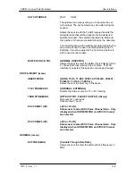
TARGET Eb/No
{4.0 to 16 dB}
This allows the user to set the desired E
b
/N
o
for the local
receiver.
RADYNE AUPC:
When configured for Radyne AUPC,
this setting is compared against the remote E
b
/N
o
and
commands to the local modem to increase or decrease
the local transmit power.
EF
AUPC:
When configured for EF AUPC, this setting
is compared against the local received E
b
/N
o
and
commands to the remote modem to increase or
decrease transmit power.
Summary of Contents for DMD50
Page 2: ......
Page 3: ......
Page 16: ...DMD50 Universal Satellite Modem Table of Contents TM118 Rev 1 1 xv...
Page 17: ......
Page 20: ...DMD50 Universal Satellite Modem Introduction TM118 Rev 1 1 1 3...
Page 21: ......
Page 27: ...Installation DMD50 Universal Satellite Modem 2 6 TM118 Rev 1 1...
Page 53: ...Theory of Operation DMD50 Universal Satellite Modem 3 26 TM118 Rev 1 1...
Page 97: ...User Interfaces DMD50 Universal Satellite Modem 4 44 TM118 Rev 1 1...
Page 122: ...DMD50 Universal Satellite Modem Rear Panel Interfaces TM118 Rev 1 1 5 25...
Page 123: ......
Page 132: ...DMD50 Universal Satellite Modem Maintenance and Troubleshooting TM118 Rev 1 1 6 9...
Page 133: ......
Page 158: ...DMD50 Universal Satellite Modem Technical Specifications TM118 Rev 1 1 7 25...
Page 159: ......
Page 162: ...DMD50 Universal Satellite Modem Appendix A TM118 Rev 1 1 A 3...
Page 163: ......
Page 170: ...DMD50 Universal Satellite Modem Appendix B TM118 Rev 1 1 B 7...
Page 171: ......
Page 174: ...DMD50 Universal Satellite Modem Appendix C TM118 Rev 1 1 C 3...
Page 175: ......
Page 184: ...DMD50 Universal Satellite Modem Appendix D TM118 Rev 1 1 D 9...
Page 185: ......
Page 192: ...DMD50 Universal Satellite Modem Appendix E TM118 Rev 1 1 E 7...
Page 193: ......
Page 200: ...DMD50 Universal Satellite Modem Appendix F TM118 Rev 1 1 F 7...
Page 201: ......
Page 205: ...Appendix G DMD50 Universal Satellite Modem G 4 TM118 Rev 1 1...
Page 224: ...DMD50 Universal Satellite Modem Appendix H TM118 Rev 1 1 H 19...
Page 225: ......
Page 231: ...Appendix I DMD50 Universal Satellite Modem I 6 TM118 Rev 1 1...


