


DMD50 Universal Satellite Modem
Appendix B
TM118 – Rev. 1.1
B-5
B.3.1 Running in Demonstration Mode
Because of the possible interruption in traffic when the demonstration mode expires, several
indicators are used to inform an operator that the modem is indeed, operating in demonstration
mode. The most obvious of these is that the remote LED is flashing.
A second indication can be found on the Features Menu as follows:
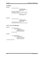
1.
From the modem’s Main Menu, scroll right to the SYSTEM Menu.
2. Scroll
down.
3.
Scroll right to the HW/FW CONFIG Menu.
4. Scroll
down.
5.
Scroll right to the FEATURES Menu. The second line will display DEMO.
A third indication can be found in the upgrade list as follows:
1.
From the FEATURES Menu.
2. Scroll
down.
3.
Scroll right to the UPGRADE LIST Menu.
4. Scroll
down.
5.
Scroll right through the available list of options.
The top line identifies the options and the second line identifies the options status.
DEMO MODE
indicates that the option is has been temporarily activated and is now available for
evaluation as part of the modems feature set.
At the end of the demonstration period, the modem will revert back to its permanent configuration.
When it does, an interrupt in traffic will occur, regardless of whether or not a demo enabled
features was being run at the time. In addition, operator intervention may be required to restore
the data paths. In order to avoid this interruption in service, the user can cancel the
demonstration at any time by following the instructions outlined in the section on Canceling
Demonstration Mode.
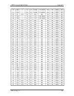
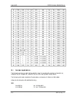
Summary of Contents for DMD50
Page 2: ......
Page 3: ......
Page 16: ...DMD50 Universal Satellite Modem Table of Contents TM118 Rev 1 1 xv...
Page 17: ......
Page 20: ...DMD50 Universal Satellite Modem Introduction TM118 Rev 1 1 1 3...
Page 21: ......
Page 27: ...Installation DMD50 Universal Satellite Modem 2 6 TM118 Rev 1 1...
Page 53: ...Theory of Operation DMD50 Universal Satellite Modem 3 26 TM118 Rev 1 1...
Page 97: ...User Interfaces DMD50 Universal Satellite Modem 4 44 TM118 Rev 1 1...
Page 122: ...DMD50 Universal Satellite Modem Rear Panel Interfaces TM118 Rev 1 1 5 25...
Page 123: ......
Page 132: ...DMD50 Universal Satellite Modem Maintenance and Troubleshooting TM118 Rev 1 1 6 9...
Page 133: ......
Page 158: ...DMD50 Universal Satellite Modem Technical Specifications TM118 Rev 1 1 7 25...
Page 159: ......
Page 162: ...DMD50 Universal Satellite Modem Appendix A TM118 Rev 1 1 A 3...
Page 163: ......
Page 170: ...DMD50 Universal Satellite Modem Appendix B TM118 Rev 1 1 B 7...
Page 171: ......
Page 174: ...DMD50 Universal Satellite Modem Appendix C TM118 Rev 1 1 C 3...
Page 175: ......
Page 184: ...DMD50 Universal Satellite Modem Appendix D TM118 Rev 1 1 D 9...
Page 185: ......
Page 192: ...DMD50 Universal Satellite Modem Appendix E TM118 Rev 1 1 E 7...
Page 193: ......
Page 200: ...DMD50 Universal Satellite Modem Appendix F TM118 Rev 1 1 F 7...
Page 201: ......
Page 205: ...Appendix G DMD50 Universal Satellite Modem G 4 TM118 Rev 1 1...
Page 224: ...DMD50 Universal Satellite Modem Appendix H TM118 Rev 1 1 H 19...
Page 225: ......
Page 231: ...Appendix I DMD50 Universal Satellite Modem I 6 TM118 Rev 1 1...


