


User Interfaces
DMD50 Universal Satellite Modem
4-8
TM118 – Rev. 1.1
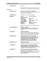
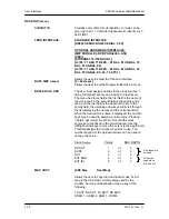
SCC CTL RATIO
{1/1, 1/2, 1/3, 1/4, 1/5, 1/6, 1/7},
Allows the user to simulate the framing used by the
Satellite Control Channel Option (Pass Thru Mode only).
The SCC CTL RATIO is the ratio of overhead in-band
data to synchronizing words.
Only displayed when SCC Framing is selected
SCC INBAND RATE
{300 to 200000}, when using SCC Framing
Allows the user to request the rate of in-band data for
the overhead channel.
Only displayed when SCC Framing is selected
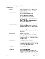
TERR FRAMING
{NONE, 188, 204}, when using DVB Network
Specifications
DATA POLARITY
{INV. TERR & BASE, INV. BASEBAND, INV.TERR
DATA, NONE}
Allows the user to invert the Tx Data polarity.
SYMBOL PAIR
{NONE, SWAPPED}
Allows the user to swap the I & Q Channels, when using
BPSK modulation.
ESC OVERHEAD
{VOICE X2, DATA 64KBPS}
IDR ESC Channel used for Voice or 64 K data channel.
Only available when IDR Network is selected.
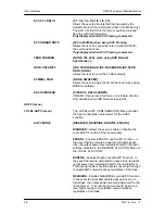
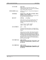
AUPC (menu)
LOCAL AUPC (menu)
The 'LOCAL AUPC CONFIGURATION' Menu contains
the local configuration parameters for the AUPC
Function.
AUPC MODE
{DISABLED, NEARSIDE, RADYNE, EFDATA}
DISABLED:
Allows the user to enable or disable the
Local AUPC Function of the local modem.
EFDATA:
Enables EFDATA Local AUPC Function. In
the event that the remote or local demodulator losses
lock, the output power level will adjust itself to the level
settings indicated in the 'REMOTE CL ACTION' Menu or
the 'LOCAL CL ACTION'.
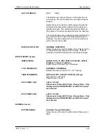
RADYNE:
Enables Radyne Local AUPC Function. In
the event the remote demodulator losses lock, the local
output power level will adjust itself to the nominal level.
This nominal power should be set to a level high enough
to re-establish communications regardless of rain fade.
NEARSIDE:
Enables NEARSIDE Local AUPC function.
In the event the local demodulator losses lock due to
signal loss, the output power level will adjust itself to the
nominal level. This nominal power should be set to a
level high enough to re-establish communications
regardless of rain fade.
Summary of Contents for DMD50
Page 2: ......
Page 3: ......
Page 16: ...DMD50 Universal Satellite Modem Table of Contents TM118 Rev 1 1 xv...
Page 17: ......
Page 20: ...DMD50 Universal Satellite Modem Introduction TM118 Rev 1 1 1 3...
Page 21: ......
Page 27: ...Installation DMD50 Universal Satellite Modem 2 6 TM118 Rev 1 1...
Page 53: ...Theory of Operation DMD50 Universal Satellite Modem 3 26 TM118 Rev 1 1...
Page 97: ...User Interfaces DMD50 Universal Satellite Modem 4 44 TM118 Rev 1 1...
Page 122: ...DMD50 Universal Satellite Modem Rear Panel Interfaces TM118 Rev 1 1 5 25...
Page 123: ......
Page 132: ...DMD50 Universal Satellite Modem Maintenance and Troubleshooting TM118 Rev 1 1 6 9...
Page 133: ......
Page 158: ...DMD50 Universal Satellite Modem Technical Specifications TM118 Rev 1 1 7 25...
Page 159: ......
Page 162: ...DMD50 Universal Satellite Modem Appendix A TM118 Rev 1 1 A 3...
Page 163: ......
Page 170: ...DMD50 Universal Satellite Modem Appendix B TM118 Rev 1 1 B 7...
Page 171: ......
Page 174: ...DMD50 Universal Satellite Modem Appendix C TM118 Rev 1 1 C 3...
Page 175: ......
Page 184: ...DMD50 Universal Satellite Modem Appendix D TM118 Rev 1 1 D 9...
Page 185: ......
Page 192: ...DMD50 Universal Satellite Modem Appendix E TM118 Rev 1 1 E 7...
Page 193: ......
Page 200: ...DMD50 Universal Satellite Modem Appendix F TM118 Rev 1 1 F 7...
Page 201: ......
Page 205: ...Appendix G DMD50 Universal Satellite Modem G 4 TM118 Rev 1 1...
Page 224: ...DMD50 Universal Satellite Modem Appendix H TM118 Rev 1 1 H 19...
Page 225: ......
Page 231: ...Appendix I DMD50 Universal Satellite Modem I 6 TM118 Rev 1 1...


