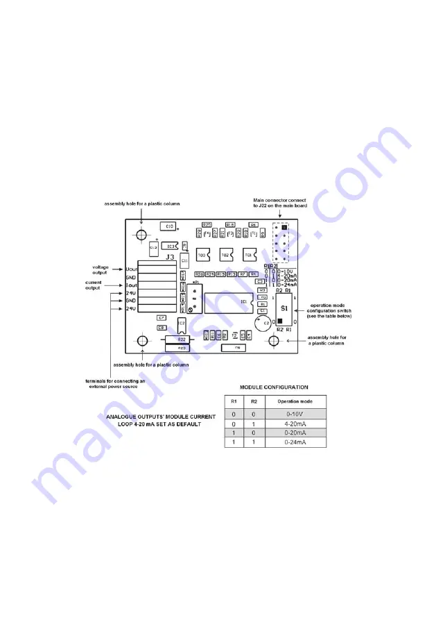
4. During installation turn your attention to plastic columns. They
should be placed one side in mounting holes in the main board
and the other side in the mounted module;
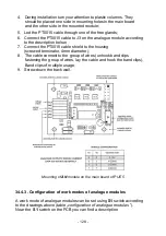
5. Led the PT0015 cable through one of the free glands;
6. Connect the PT0015 cable to J3 on the analogue module according
to the description below;
7. Connect the PT0015 cable shield to the housing
(screwed terminator, 4mm diameter);
8. The cable connect to the group of wires (unhook band clips
fastening the group of wires, lay the cable and hook the band clips).
Band clips of multiple usage;
9. Screw down the back wall.
Mounting of AN module on the main board of PUE 5
34.4.3. Configuration of work modes of analogue modules
A work mode of analogue modules can be set using
S1
switch according
to the drawings above
(
table „
configuration of analogue modules
”).
Near the
S1
switch on the PCB you can find a description
- 128 -
Summary of Contents for TMX series
Page 2: ... 2 SEPTEMBER 2011 ...


