


1997 Radionics All rights reserved
The Radionics logo is a registered trademark of Radionics,
1800 Abbott Street, Salinas, CA 93901, USA
74-07649-000-B 01/97
D9024/D10024 Installation
Page 10 of 17
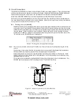
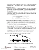
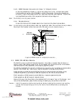
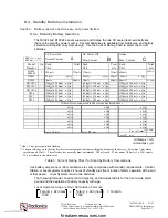
C.2.d. D9067 Module Connection to Class “A” (Style 6) Circuit
Connect the Data/Power Positive (+) wire of the polling circuit to the + terminal of the Data
Terminal Block at the top of the D10024M Control Communicator. Connect the Data/Power
Common (-) wire of the polling circuit to the - terminal of the Data Terminal Block. Connect the
returning Data/Power wires to the respective terminals as shown in
Figure 9
.
Note: The Polling circuit is power-limited
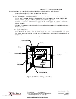
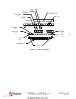
C.2.e. Shielded Cable
Connect the drain wire for shielded cable to the E terminal of the Data Terminal Block.
Note: An improperly grounded shielded cable may aggravate rather than eliminate noise problems.
Reconnect the shielded cable drain each time the cable is cut to install a device.
MODULE
MODULE
POLLING
POLLING
CIRCUIT
D9067
+
E
-
-
+
LOOP
2
CIRCUIT
D9067
- LOOP
1
Earth Ground for
Shield Cable Drain
Data/Power Positive Return
Data/Power Common Return
Data/Power Positive Out
Data/Power Common Out
Figure 9: D9067 Class “A” (Style 6) Connection
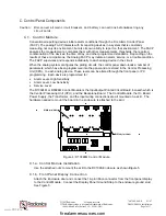
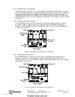
C.3. D9051 RS 485 Bus Module
The D9051 module is an RS 485 Network Expander. It provides an isolated Class B, Style 4 or
Class A, Style 6 data interface between the Control Module and Command Centers, Annunciators,
networked panels, serial peripherals, and computer graphics systems.
The D9024 and D10024 Fire Alarm Control Panels can support up to 31 peripheral communications
devices on the RS485 bus. Each device must be assigned an individual binary address.
Port D
supports a peripheral circuit for D9069 remote annunciators, D9070 controllers, 4-way
notification appliances, synchronized notification appliances, and other serial peripherals.
Port C
supports an RS 485 panel-to-master data link, or panel-to-graphics data link.
Port B
supports an RS 485 output to network panels.
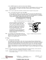
Remove AC power from the system at the dedicated 120
V
AC breaker, “lock out” the breaker, and
remove the standby battery power before making or breaking any connections to the FACP.
Caution: Inform the operator and the local authority before installing this module in an existing
system. Disconnect all power to the Fire Alarm Control Panel before installing this
module.
www.PDF-Zoo.com
firealarmresources.com


