

1997 Radionics All rights reserved
The Radionics logo is a registered trademark of Radionics,
1800 Abbott Street, Salinas, CA 93901, USA
74-07649-000-B 01/97
D9024/D10024 Installation
Page 15 of 17
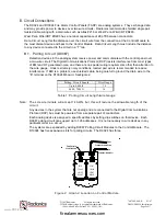
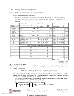
Total Ah x 1.1 = Total Ah Requirements
Maximum battery size permitted to be connected to the D9024 or D10024 is 38 Ah.
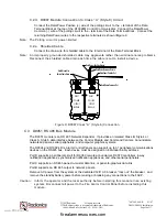
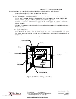
Place the batteries in the enclosure as shown in
Figure 14,
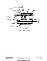
D.3.b. Battery Wiring Connections
The D10024 Literature Package contains a gray wire. Use this wire to connect the positive
terminal of battery No. one to the negative terminal of battery No. two.
Connect the red wire lead from terminal (6) on the Power Supply to the positive terminal of
battery No. two.
Connect the black wire lead from terminal (7) on the Power Supply to the negative terminal of
battery No. one.
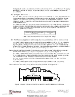
D.4. System Startup
Close the 120
V
AC dedicated breaker that controls the power input to the D10024. The green
AC Power LED lights to show that the 120V AC power supply is on and the standby battery is
connected.
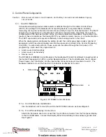
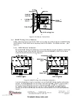
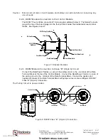
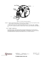
Standby
Batteries
120 V AC Connection Point
Mains Fuse
Control Module
24 V DC Power Supply Fuses
Display Panel
Ground Strap
16-Pin Ribbon Connector
Display Card
Figure 14: Standby Battery Installation
www.PDF-Zoo.com
firealarmresources.com