


1997 Radionics All rights reserved
The Radionics logo is a registered trademark of Radionics,
1800 Abbott Street, Salinas, CA 93901, USA
74-07649-000-B 01/97
D9024/D10024 Installation
Page 6 of 17
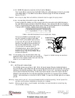
Polling circuits can be connected to the FACP as either a Class “A” or a Class “B” circuit. “T” tapping
is acceptable in Class “B” circuits. For specific Class “A” and “B” circuit installation requirements,
see NFPA 72.
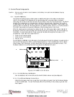
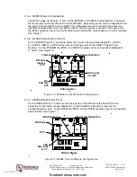
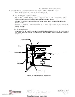
B.2 Peripheral Circuits
The RS 485 Bus Circuit provides an optically isolated data interface between the Control Module and
Command Centers and Annunciators, networked panels, serial peripherals, and computer graphics
systems. A shielded twisted pair wiring circuit connects to the D9051 RS 485 Bus Module. The
three ports on the left side of the control module are mounting points, depending on the application,
for the D9051 Modules.
The D9052 RS 232 Module provides an isolated interface between the Control Module and dial-up or
dedicated modems. Modems allow communication over telephone lines between networked panels,
system controllers, computer graphics packages, and other serial peripherals when the circuit
distance is greater than 3,250 feet.
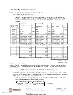
RS 485 Peripheral Circuit Length
Wire Gauge
Up to 4,920 ft.
18
Table 2: RS 485 Peripheral Circuit Length/wire Gauge
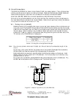
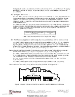
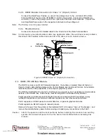
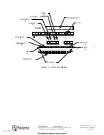
B.3 Notification Appliance (Indicating Device) and Output Circuit Connections
The D9024 and D10024 each has four power-limited and supervised Class “B,” Style “W” indicating
circuits. The terminal blocks for these circuits are at the lower edge of the Control Module. (See
Figure 3
.) Each indicating circuit must be terminated with a 2k End Of Line (EOL) resistor (Part No.
25899C, manufactured by Detection Systems). Four resistors for the indicating circuits are included
in the Literature Pack. Each circuit has a maximum rating of one Amp.
See Compatible Device List:
Devices Compatible with the D10024 Analog Fire Alarm Control Panel
,
Part No. 73-07674-000-A, for devices acceptable for use in the indicating circuit.
The D9024 and D10024 each has terminals for a power-limited auxiliary 24 V circuit at the lower left
of the Control Module. This circuit is rated at one Amp maximum. If the system requires more than
four circuits use the D327 Indicating Circuit Module to add circuits as required.
The total current of the five circuits (four “SOUNDER OUTPUTS” PLUS “24V AUX.”) must not
exceed two Amps.
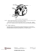
The D9024 and D10024 each has two programmable relay contacts rated 24 V DC, 1 Amp.
Caution: Do not connect any wiring that is not power-limited to the relay contacts.
AUX RELAYS
RELAY 2
RELAY 1
24V. AUX
O
V.
24
V.
SOUNDER
OUTPUTS
A-
A+
B-
B+
C-
C+
D-
D+
N/C
N/O
COM
N/C
N/O
COM
Figure 3: Output Connection Points on the D9024 and D10024M Control Module
www.PDF-Zoo.com
firealarmresources.com