background image

1997 Radionics                                      All rights reserved

The Radionics logo is a registered trademark of Radionics,

    1800 Abbott Street, Salinas, CA  93901, USA

74-07661-000-B      01/97
D9024/D10024 Operation


Page 11 of 13

To change from the prompted number of days, press the CHANGE key, enter the desired

number of days, and press the ENTER key.
Enter zero (0) days to disable the Delayed Day Mode.
Enter 200 days to permanently enable the Delayed Day Mode.
If the Delayed Day Mode has not been programmed into the panel, pressing option four from

the Enable or Disable Menu will result in a “Not available” message on the Alphanumeric

Display.

D.4.c.5.  Enable Disable Relays

Select option five, 5) Disable, from the Main Level of the Operator’s Menu to disable relays

during testing.  The panel displays the Disable Menu.
Select option five, 

5) Outputs

.

The Display Shows:

1) Sounders          2) Relays

          ENABLED           ENABLED

Select 

Relays

, option two.

The panel buzzer sounds, the 

System Trouble 

LED lights, and the Alphanumeric Display

message indicates that the relays are disabled.
Press the 

Trouble Silence


key to silence the buzzer.  The 

Trouble Silenced 

LED will light.

Note: The disabled output must be enabled before the system can be reset.

To enable the outputs, press the

 NO

  key to revert to the main menu.

Enter the Enable Menu by selecting option four, 

4) Enable

.  Select option five

, 5) Outputs

.

Select 

Relays

, option two.  The system will reset, and the 

Trouble Silenced 

LED will go out.

Press the 

NO

 key to return to the main menu.

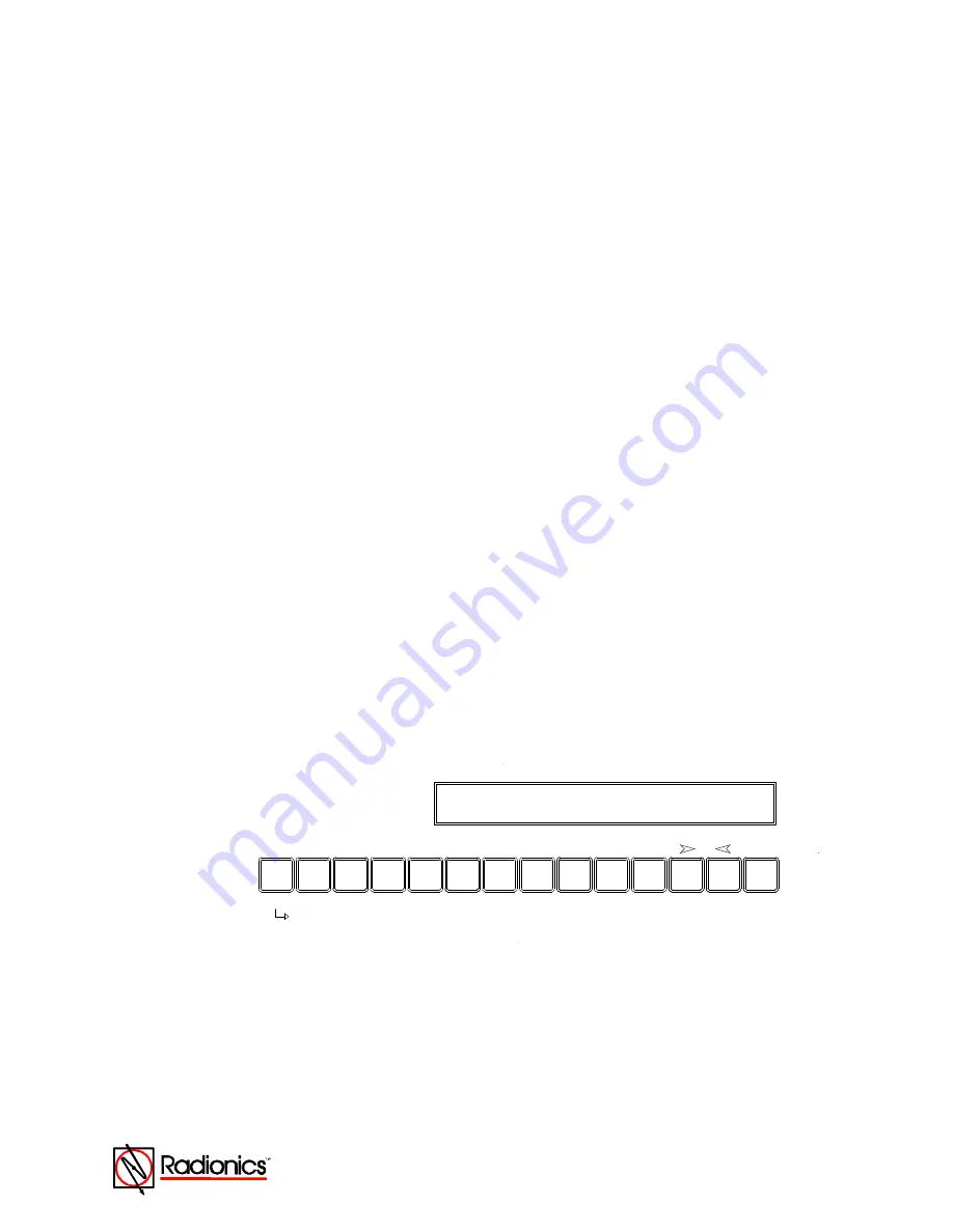
D.4.d.  Print Functions

Enter the Print Menu from the Main Level of the Operator’s Menu by selecting option six, 

6)

Print

.  This menu controls the operation of the front panel printer.

D10024

SHIFT

G

T

6

PRINT :    1) Devices    2) Events  3) Disabled
( Manual ) 4) Mode       5) Direction (v)

O

A

N

0

B

C

P

1

2

D

Q

E

R

3

4

F

S

5

H

U

7

V

I

J

W

8

9

K

X

L

Y

M

Z

CHANGE

Figure 6:  Print Menu

D.4.d.1  Print Devices

Option one on the Print Menu allows the operator to print out the current state and the text

assigned to all devices on a polling circuit (loop).

D.4.d.2.  Print Event Log

Option two on the Print Menu allows the operator to print out the contents of the event log.

Summary of Contents for D9024

Page 1: ...nt to Part 15 of the FCC Rules These limits are designed to provide reasonable protection against harmful interference in a commercial installation This equipment generates uses and can radiate radio...

Page 2: ...ble Signal Response 6 D 3 Alarm Conditions 6 D 3 a Alarm Signals 6 D 3 b Alarm Signal Response 7 D 4 Operator s Menu 7 D 4 a System Tests 8 D 4 a 1 LEDs Test 8 D 4 a 2 Walk Test 8 D 4 b Time Setting 9...

Page 3: ...of Radionics 1800 Abbott Street Salinas CA 93901 USA 74 07661 000 B 01 97 D9024 D10024 Operation Page 3 of 13 Figure 1 Front Panel Display 4 Figure 2 Level Two Controls 7 Figure 3 Operator s Menu Main...

Page 4: ...on on system events and status and displays interactive prompts The middle display is a row of LEDs that indicate the type of system event and status The lower display area is the ZONE AREA LED displa...

Page 5: ...by 120 V AC the greenAC PowerLED at the right end of the LED Display will be lit The normal Alphanumeric Display will alternate between a time and date message and a system status message If the 120...

Page 6: ...the amberSystem Troubleor Fault LED will light In addition the amber Trouble LED in the ZONE AREA section of the panel will light to indicate the location the panel s internal buzzer will sound and t...

Page 7: ...ing theAlarm Silencekey again turns on the external notification appliances Press theTrouble silencekey to turn off the panel buzzer The amberTrouble Silenced LED will light Press theSystem Reset key...

Page 8: ...V I J W 8 9 K X L Y M Z CHANGE Figure 4 Test Menu D 4 a 1 LEDs Test Select the first option 1 LEDs by pressing the1 key The panel will flash all LEDs on the LED Display and step through all theAlarm a...

Page 9: ...the LED at the device in alarm After a few seconds the panel will automatically reset and turn off the device LED The panel allows up to one minute for smoke devices to clear The operator may then te...

Page 10: ...cuit number and press ENTER The display then prompts for the address of the device Key in the address and press ENTER The display repeats the circuit number and address Press the YES key Note Any disa...

Page 11: ...e Alphanumeric Display message indicates that the relays are disabled Press theTrouble Silencekey to silence the buzzer TheTrouble SilencedLED will light Note The disabled output must be enabled befor...

Page 12: ...tion about the selected option on the Alphanumeric Display After viewing an option press theNO key to return to the View Menu Press the NO key again to return to the Main Level of the Operator s Menu...

Page 13: ...oning and programming the Fire Alarm Control Panel E 1 Disable Enable Sounders Notification Appliances All sounders notification appliances and relays can be disabled or enabled from the control panel...

Reviews: