background image

5

Chapter 5. Firmware update

1. Press and hold the firmware update button(do not supply power to the encoder). Then connect
the encoder to the computer via USB, the blue light will start to flash. Release the firmware update
button.
2. The computer pops up a window asking whether the U disk needs to be formatted, and you can
directly close the window.
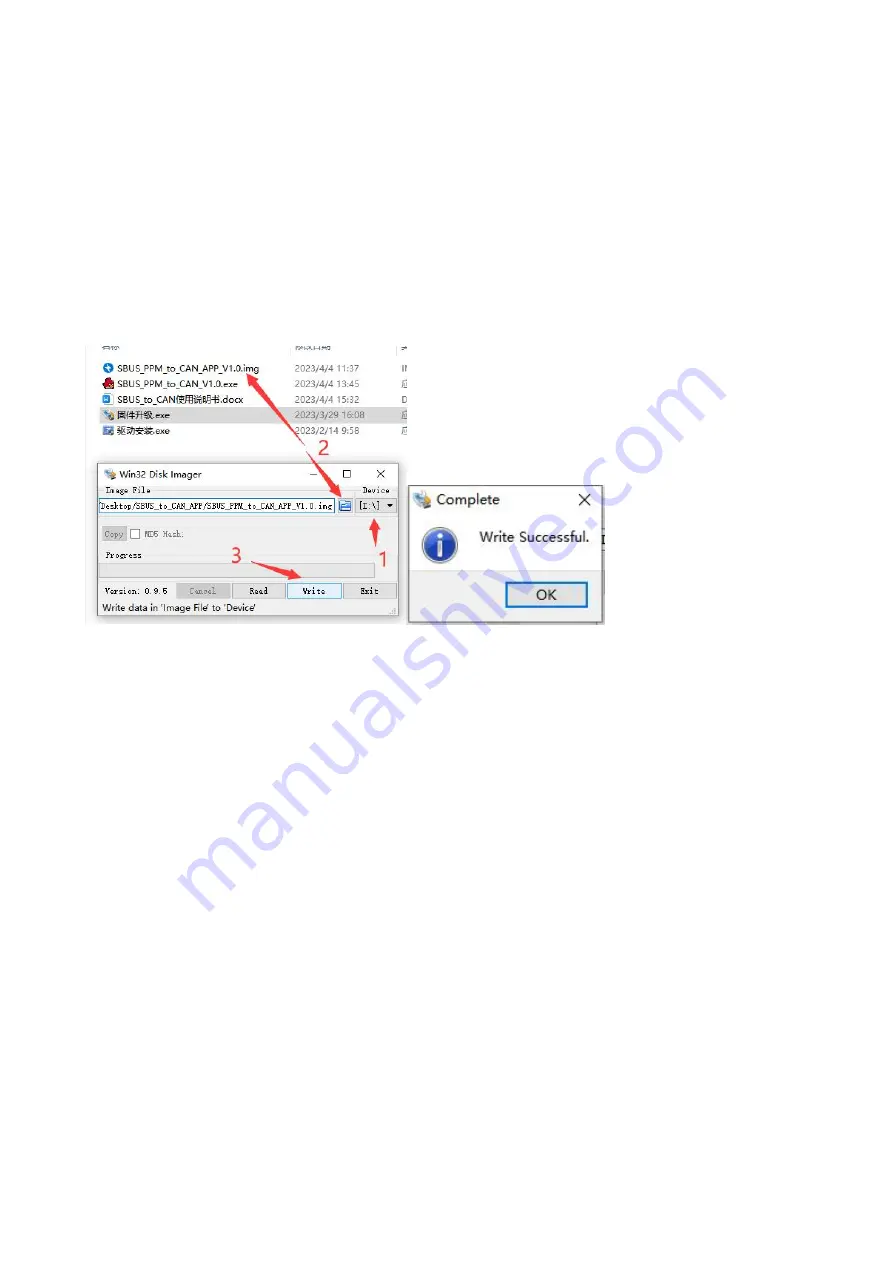
3. Open the firmware upgrade software.

(1) Select the disk that just popped up.
(2) Select the firmware to be updated.
(3) Write the program, and it will pop up “Write Successful”.
(4) Unplug and re-insert the USB to confirm whether the upgrade is successful.

Note: If the blue light is on and the red light flashes quickly after power-on again, the firmware is
abnormal. Please confirm that the firmware is correct, and then repeat the above update
operation.

Summary of Contents for RTC8

Page 1: ...RTC8 SBUS PPM to CAN Protocol Encoder...

Page 2: ...1 Contents Chapter 1 Overview 2 Chapter 2 Specifications 3 Chapter 3 Main Functions 3 Chapter 4 Driver installation 4 Chapter 5 Firmware update 5 Chapter 6 SBUS PPM to CAN Explorer 6...

Page 3: ...e mode 4 Power Indicator Lights up in green after the encoder is powered on 5 USB connector 1 Connect with computer for parameter adjustment and data observation 2 Update the firmware after connecting...

Page 4: ...ication baud rate can be freely programmed between 5Kbps 1Mbps 5 Powered by USB 5 15V 6 The received data flow rate is up to 100fps 7 Support Windows 7 8 9 10 and other Windows systems 8 Support SBUS_...

Page 5: ...Chapter 4 Driver installation 1 Use a USB cable to connect the SBUS PPM to CAN Protocol encoder to the computer 2 After the successful connection there will be a new COM port in computer device manage...

Page 6: ...o be formatted and you can directly close the window 3 Open the firmware upgrade software 1 Select the disk that just popped up 2 Select the firmware to be updated 3 Write the program and it will pop...

Page 7: ...atus information display 1 CAN Display currently received CAN data after filtering ID 2 SBUS If there is an SBUS signal input the SBUS channel data will be displayed 3 PPM If there is a PPM signal inp...

Page 8: ...eters will not be set successfully 1 CAN Timing Preset baud rate selection After selection BS1 BS2 BRP and SJW parameters will be automatically set When the preset value does not meet the requirements...

Page 9: ...Get 8byte_1 ID and send 8 data 1 4 channels 2 bytes per channel 3 Respond after receiving Get 8byte_2 ID and send 8 data 5 8 channels 2 bytes per channel 4 Respond after receiving the Get 8byte_3 ID...

Page 10: ...as follows The meaning of each bit in Filter Mask ID 1 Bit x is set to 1 and the bit x of the received ID must be consistent with the bit x of the Filter ID otherwise it will be ignored 2 Bit x is set...

Page 11: ...User Mode Parameters 1 Length User defined data sending length 2 Remote Request 3 Cycle Time The cycle of automatically sending channel data 4 AutoSender Automatic sending mode When AutoSender is tic...

Reviews: