— 41 —
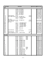
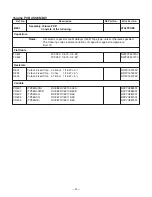
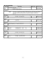
Assembly, MIC PCB
Consists of the following:
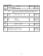
MIC PCB ASSEMBLY
Ref. No.
Description
RS Part No.
Mfr’s Part No.
B751
AT367ZHBE
Capacitors
Notes:
All ceramic capacitors are Multilayer (1608) Tape type, unless otherwise specified.
The following codes indicate variations of capacitors against temperature:
B=
±
10%
Flat Cable
FC751
WF-351
3.5-70-3.5 5P
BWFY3510700
Jacks
J751
MIC
3JK-1139
BJKY1139001
Resistors
R751
Carbon Fixed Chip
4.7 kohm 1/16 W
±
5 %
BRFC164724Z
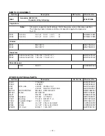
Capacitor
C801
Ceramic
0.0056
µ
F 50 V
±
10 %
B
BCML815625Z
C802
Ceramic
0.0056
µ
F 50 V
±
10 %
B
BCML815625Z
Flat Cable
FC801
WF-350
3.5-70-3.5 3P
BWFY3500700
Switch
S801
Rotary
SR-456
EC09P20-303A0
BSRY0456001
Summary of Contents for TRC-447
Page 5: ...5 BLOCK DIAGRAM...
Page 16: ...16 WIRING DIAGRAM...
Page 17: ...17 PRINTED CIRCUIT BOARDS Main Top View...
Page 18: ...18 Bottom View...
Page 19: ...19 SWITCH VOLUME LED MIC CH SW SWR PCBs Top View Bottom View...
Page 21: ...21 5 13 20 1 21 9 10 26...
Page 22: ...22 12 11 18 23 24 25 19 18 20 3 20 9 20 5 20 10 20 11 20 3 20 12 20 13 20 14 20 12...
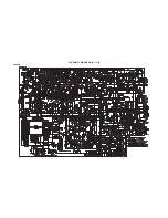
Page 50: ...51 50 SCHEMATIC DIAGRAMS 21 1576 Main PCB...
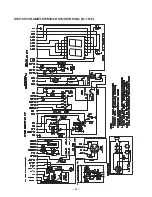
Page 51: ...52 SWITCH VOLUME LED MIC CH SW SWR PCBs 21 1576...
Page 52: ...RadioShack Corporation Fort Worth Texas 76102 21 1576 04A04 Printed in Japan...


