— 12 —
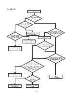
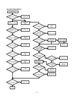
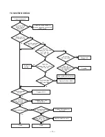
PLL CIRCUIT
CB No good
OK
Check whether there
is RF voltage at
R58 (L7 side).
NG
Check whether there
is RF voltage at pin11
of IC301.
Check whether voltage
reading at pin15 of
IC301 is approx. 5.0 V.
Defective R10, L101, C152
or poor soldering.
Check whether there is
approx. 2.3 V at CH1 (RX) and
3.8 V at CH40 (TX) at TP3.
Adjust L301.
Defective Vcc line (5.0 V) at
R316 or D303.
Defective Q301, 302, 303
L301 or poor soldering.
Check whether there is
approx. 2.3 V at CH1 (RX) and
3.8 V at CH40 (TX) at TP3.
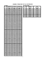
Check whether each channel
frequency matches the frequency
indicated in frequency chart.
Check whether there are
pulses at pin13 of IC401 when
rotating the CH rotary switch upward, or
there are pulses at pin14 of IC401
when rotating the CH rotary
switch downward.
Good
PLL is not defective.
Check whether there is
RF voltage at
pin16 of IC301.
Defective IC401 or poor
soldering.
Defective crystal X301 or
poor soldering.
Defective IC301 or poor
soldering.
NG
OK
NG
OK
NG
OK
NG
OK
NG
OK
OK
NG
NG
OK
Summary of Contents for TRC-447
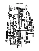
Page 5: ...5 BLOCK DIAGRAM...
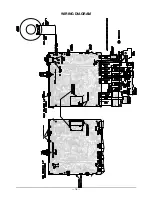
Page 16: ...16 WIRING DIAGRAM...
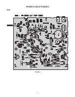
Page 17: ...17 PRINTED CIRCUIT BOARDS Main Top View...
Page 18: ...18 Bottom View...
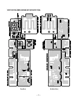
Page 19: ...19 SWITCH VOLUME LED MIC CH SW SWR PCBs Top View Bottom View...
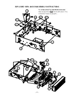
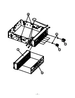
Page 21: ...21 5 13 20 1 21 9 10 26...
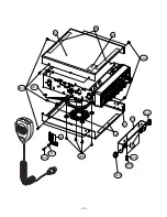
Page 22: ...22 12 11 18 23 24 25 19 18 20 3 20 9 20 5 20 10 20 11 20 3 20 12 20 13 20 14 20 12...
Page 50: ...51 50 SCHEMATIC DIAGRAMS 21 1576 Main PCB...
Page 51: ...52 SWITCH VOLUME LED MIC CH SW SWR PCBs 21 1576...
Page 52: ...RadioShack Corporation Fort Worth Texas 76102 21 1576 04A04 Printed in Japan...


