— 14 —
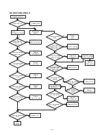
RX SECTION CHECK
Does not receive.
Check ANT jack.
OK
If C
RF GAIN VOL MAX.
B.
If WX/Digital
SAME.
Check
whether there is RF
voltage at TP7 and
2nd Local.
Check the voltage
at pin9 of IC102.
Check the voltage
at Pin 1 of IC102.
Replace
IC102 or L103.
waveform at Pin9
Check the
of IC102. (SSG
3 kHz)
Replace IC102.
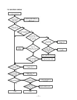
Check the WX SQ
operation.
Check the voltage
of D101.
the peripheral
circuit.
Replace D101.
If the digital/SAME
OPERATION
Check the voltages
at Q101 and 102.
Replace IC104.
Check the voltages of
IC104.
Check the voltages
of Q1 ~ Q5.
Check the connection
of TP1.
Good
Adjust L103
(See page 8).
Resolder TP1.
Replace
Q1 ~ Q5.
See PLL section.
NG
Replace J501.
Check the
voltage of TP4 1 to 4V
at WX C
Check the voltage
D201.
H7.
See PLL section.
Check the voltages
of Q6, 8 and 9.
Replace
Q6, 8 and 9.
Replace
Q101 and 102.
OK
OK
OK
OK
NG
NG
NG
Check the voltages
of Q11, D7, D8.
Replace
Q11, D7 or D8.
Check the voltages
of D202.
Check the voltages
of D3.
Replace
D3.
Replace
D202.
OK
OK
OK
NG
NG
NG
NG
NG
NG
NG
NG
NG
NG
Replace
defective parts.
NG
NG
OK
OK
OK
OK
OK
OK
NG
NG
OK
OK
OK
OK
NG
NG
NG
OK
Replace
D201.
OK
OK
modulation
Check
Summary of Contents for TRC-447
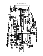
Page 5: ...5 BLOCK DIAGRAM...
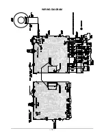
Page 16: ...16 WIRING DIAGRAM...
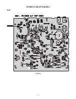
Page 17: ...17 PRINTED CIRCUIT BOARDS Main Top View...
Page 18: ...18 Bottom View...
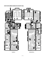
Page 19: ...19 SWITCH VOLUME LED MIC CH SW SWR PCBs Top View Bottom View...
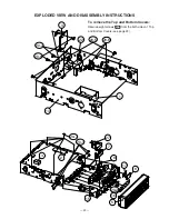
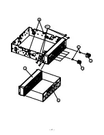
Page 21: ...21 5 13 20 1 21 9 10 26...
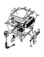
Page 22: ...22 12 11 18 23 24 25 19 18 20 3 20 9 20 5 20 10 20 11 20 3 20 12 20 13 20 14 20 12...
Page 50: ...51 50 SCHEMATIC DIAGRAMS 21 1576 Main PCB...
Page 51: ...52 SWITCH VOLUME LED MIC CH SW SWR PCBs 21 1576...
Page 52: ...RadioShack Corporation Fort Worth Texas 76102 21 1576 04A04 Printed in Japan...


