— 11 —
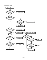
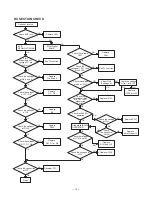
AUDIO SECTION
Check if
speaker wiring is
connected
properly.
NG
No
RX sound
Replace or resolder.
Check if
volume, squelch
controls are adjusted
properly.
NG
Check volume and
wire connections.
NG
Replace wire or resolder.
OK
Adjust volume and
squelch control.
OK
Check IC501
AF power IC and Q10.
NG
NG
NG
Replace IC501 AF power IC
and/or Q10.
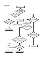
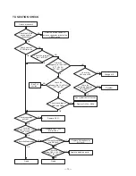
Change CB/WX/PA
switch to PA.
Good.
PA function is good.
Connect PA speaker and PTT on.
Input 1kHz signal to MIC.
Check if Q7
voltages are as shown
in voltage chart.
NG
Replace
defective parts.
NG
Resolder.
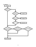
Che
If CB
If PA
ck Q7 and
associated circuit.
Check
Q6, 8, 9, and 12
voltages are as shown in
voltage
chart.
NG
Check microprocessor
section.
Check RF section.
OK
OK
Sound from
PA speaker?
OK
OK
OK
OK
OK
Check voltage
of Q204, Q206,
Q208, Q209.
Check PA
or CB/WX/PA switch
connection.
speaker
Summary of Contents for TRC-447
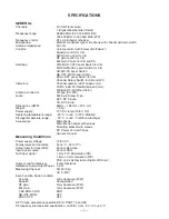
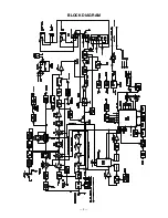
Page 5: ...5 BLOCK DIAGRAM...
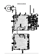
Page 16: ...16 WIRING DIAGRAM...
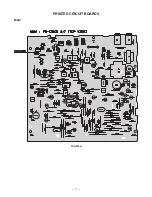
Page 17: ...17 PRINTED CIRCUIT BOARDS Main Top View...
Page 18: ...18 Bottom View...
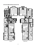
Page 19: ...19 SWITCH VOLUME LED MIC CH SW SWR PCBs Top View Bottom View...
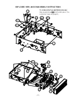
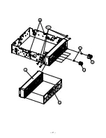
Page 21: ...21 5 13 20 1 21 9 10 26...
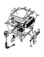
Page 22: ...22 12 11 18 23 24 25 19 18 20 3 20 9 20 5 20 10 20 11 20 3 20 12 20 13 20 14 20 12...
Page 50: ...51 50 SCHEMATIC DIAGRAMS 21 1576 Main PCB...
Page 51: ...52 SWITCH VOLUME LED MIC CH SW SWR PCBs 21 1576...
Page 52: ...RadioShack Corporation Fort Worth Texas 76102 21 1576 04A04 Printed in Japan...


