— 10 —
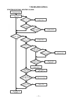
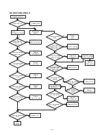
Unit will not tum on
Check the voltage
of IC502.
Power ON
NG
Check the power
SW VR601.
NG
Replace IC502.
OK
OK
OK
Is display normal?
Check the voltage
at IC502.
Replace IC502.
NG
Replace Fuse.
NG
OK
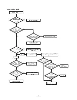
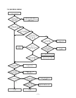
Check the
oscillation at pin
26 of IC401.
Check the
voltage at pin 25
of IC401.
Check the voltages
of IC403.
Replace IC403.
NG
OK
Check the
voltages of IC402
and Q401.
OK
Replace IC402
and/or Q401.
NG
Replace X401.
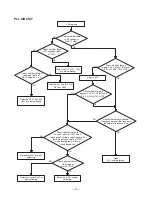
the voltages
of Q407, Q404
and Q405.
OK
Replace Q407
and/or Q404, Q405.
NG
Check
Check the
soldering of the cable
between MAIN and FRONT
PCBs.
Replace soldering.
NG
NG
NG
NG
NG
OK
OK
OK
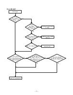
Check the
voltage of D703.
Replace D703.
NG
Check the Fuse.
OK
Check RX and TX
sections.
OK
OK
TROUBLESHOOTING
SYSTEM CONTROL SECTION CLOCK
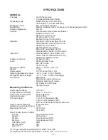
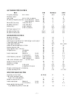
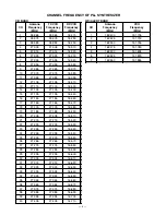
Summary of Contents for TRC-447
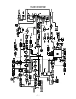
Page 5: ...5 BLOCK DIAGRAM...
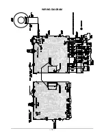
Page 16: ...16 WIRING DIAGRAM...
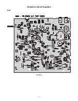
Page 17: ...17 PRINTED CIRCUIT BOARDS Main Top View...
Page 18: ...18 Bottom View...
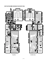
Page 19: ...19 SWITCH VOLUME LED MIC CH SW SWR PCBs Top View Bottom View...
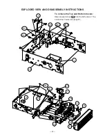
Page 21: ...21 5 13 20 1 21 9 10 26...
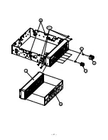
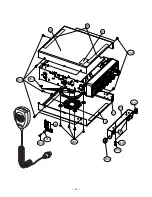
Page 22: ...22 12 11 18 23 24 25 19 18 20 3 20 9 20 5 20 10 20 11 20 3 20 12 20 13 20 14 20 12...
Page 50: ...51 50 SCHEMATIC DIAGRAMS 21 1576 Main PCB...
Page 51: ...52 SWITCH VOLUME LED MIC CH SW SWR PCBs 21 1576...
Page 52: ...RadioShack Corporation Fort Worth Texas 76102 21 1576 04A04 Printed in Japan...


