VBOX 3iSL User Guide
Page 23 of 49
01/12/2011
RS232 Serial / CAN
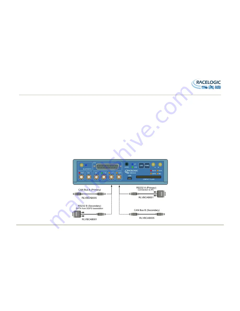
VBOX 3iSL is equipped with 2 CAN Bus interfaces and 2 RS232 serial ports. The primary RS232 port is used for all communication between the VBOX and laptop
PC. The primary port is marked RS232 on the VBOX 3i front panel. The primary RS232 port is able to transmit live data from the VBOX to the PC for viewing and
performing real-time tests. It is important to note however that due to limitations of the PC serial port, live data transfer of all channels is limited to 20Hz, at 50Hz only
standard GPS channels should be transmitted, and at 100Hz only Sats, Time, Speed, and Trigger Event Time should be transmitted. Logging too many channels at
too high a rate is likely to cause drop-outs and loss of data.
Therefore for maximum accuracy, tests performed at a GPS sample rate above 20Hz should be logged to compact flash and post processed.
The secondary RS232 port is used for connection to a Telemetry Radio module allowing the reception of Differential GPS (DGPS) data for local correction from a
Racelogic Local DGPS basestation. The secondary RS232 port is located in the connector marked CAN on the VBOX 3iSL front panel.
The CAN Bus ports A and B are located in the VBOX 3iSL
connectors “CAN” and “RS232” respectively. The function of these ports is configurable by the user for
use by either Racelogic external modules or the users own CAN Bus equipment. For dual use of RS232 and CAN from one of the sockets you will require a 5Way
Lemo splitter RLVBACS024.
Power supplied to external Racelogic CAN modules through the “CAN” or “RS232” cables is at the same voltage as the input power supply. Therefore
when using Racelogic external CAN modules (eg; MFD or ADC03), the VBOX 3I supply voltage must not exceed 15vDC.

