background image

www.moleculardevices.com

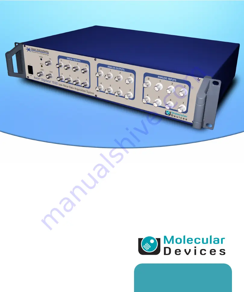
Digidata® 1550

Low-Noise Data Acquisition System

User Guide

5023399 A

April 2013

Summary of Contents for Digidata 1550

Page 1: ...www moleculardevices com Digidata 1550 Low Noise Data Acquisition System User Guide 5023399 A April 2013...

Page 2: ...y such usage is intended only to designate those manufacturers products as supplied by Molecular Devices for incorporation into its equipment and does not imply any right and or license to use or perm...

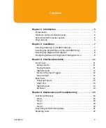
Page 3: ...data 1550 Digitizer 8 Configuring Software for Digidata 1550 Digitizer Use 8 Chapter 3 Interface Description 11 Front Panel 11 Analog Inputs 11 Analog Outputs 11 Digital Outputs 12 Start and Tag Input...

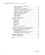
Page 4: ...izer does not work properly 25 Data throughput problems 26 Contacting Support 26 Before you call 26 Appendix A Specifications 29 Analog Inputs 29 Analog Outputs 29 Digital Inputs 30 Digital Outputs 30...

Page 5: ...are eight digital output lines as well as TAG and START digital inputs The Digidata 1550 digitizer communicates with the host computer using USB 2 0 The Digidata 1550 digitizer is a plug and play devi...

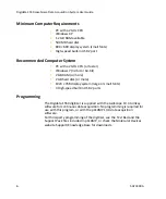
Page 6: ...RAM or more 2 GB hard disk or more 1024 768 display system large or small fonts 3 High speed built in USB 2 ports Programming The Digidata 1550 digitizer is supplied with the AxoScope 10 4 turnkey sof...

Page 7: ...550 Digitizer Use on page 8 Installing AxoScope or pCLAMP Software Install the AxoScope 10 4 or pCLAMP 10 4 software which includes the Digidata 1550 digitizer drivers An AxoScope 10 4 software CD is...

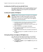
Page 8: ...er warm up for one hour before performing experiments 5 Windows automatically finds the new hardware and installs the drivers 6 Configure AxoScope 10 4 or pCLAMP 10 4 software for use with the digitiz...

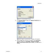
Page 9: ...idata 1550 Series from the Digitizer Type list Figure 2 2 Digitizer Type Selection of Digidata 1550 digitizer 4 Click the Scan button to detect the digitizer The Configuration message changes from una...

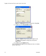
Page 10: ...ing Scan 5 Click OK to exit the Change Digitizer dialog Figure 2 4 Digitizer dialog displaying active digitizer mode The Digitizer dialog appears showing the currently active digitizer mode 6 Click OK...

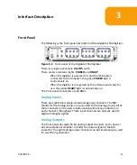
Page 11: ...for use the yellow READY light is continuously on The front panel connectors are all BNCs Analog Inputs There are eight 16 bit single ended analog input channels The BNC shields for the Analog Inputs...

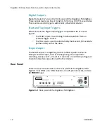
Page 12: ...gin data acquisition from an external trigger source The TAG input is used to automatically mark events for example perfusion ON within the data Scope Output The SCOPE output is a digital signal that...

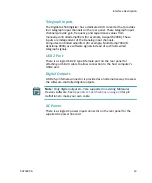
Page 13: ...lamp 900A use software signals instead of such hard wired telegraph signals USB 2 Port There is a single USB 2 0 type B female port on the rear panel for attaching a USB 2 0 cable to allow connection...

Page 14: ...Digidata 1550 Low Noise Data Acquisition System User Guide 14 5023399A...

Page 15: ...e safety information in this guide See Appendix C Safety Guide on page 35 The following topics describe maintenance and troubleshooting procedures that can be performed by users to ensure optimum oper...

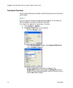
Page 16: ...itizer is properly installed in Windows To configure the digitizer for AxoScope or Clampex 1 Click Configure Digitizer 2 If Digidata 1550 Series is not displayed Click the Change button In the Change...

Page 17: ...ber should match the number on the barcode label of the unit The Power on Holding Levels section is used to set the voltage on the Analog Out channels at the time that the Digidata 1550 Low Noise Data...

Page 18: ...er 3 Expand the Universal Serial Bus controllers tree 4 If you do not have an entry for USB 2 then look for Enhanced PCI to USB Host Controller Enhanced is a key word indicating a USB 2 0 controller S...

Page 19: ...signal for example OUT 1 from its list 3 Attach the digitizer s outputs to an oscilloscope or 10 bit digital volt meter DVM 4 For each output signal use the software s Real Time Control panel to chang...

Page 20: ...puts tab for each of the Analog IN Channels select the matching signal for example IN 0 from its list 3 Connect a BNC cable from the analog outputs to the analog inputs to be tested 4 Click the Record...

Page 21: ...ric motor such as found in a nearby fan or refrigerator Try to rearrange the two BNC cables to determine if their positioning tells you anything about the source of the alternating field High frequenc...

Page 22: ...f power replace the fuses If you do not have spare fuses you can obtain them from Molecular Devices For Digidata 1550 digitizer fuse specifications see AC Power on page 32 The Digidata 1550 digitizer...

Page 23: ...Technical Support regarding problems please review this section to see if you can address the problem yourself For more information see Contacting Support on page 26 for faster resolution of your prob...

Page 24: ...ol Use a voltmeter or oscilloscope to examine the output signals Problems With Analog or Digital Inputs Check the Lab Bench and protocol Connect a known signal source to an analog input such as a sign...

Page 25: ...range behavior Double check that you are using a USB 2 0 braided shielded cable Improper shielding can lead to USB communication problems that manifest in a variety of odd behaviors ranging from minor...

Page 26: ...rformance problems in Clampex or AxoScope try the following In Configure Lab Book Options select Never log any events In Configure Program Options select Disable screen saver during data acquisition C...

Page 27: ...digitizer For example Clampex 10 4 0 1 Click Help About Clampex 4 If you can reproduce a problem by following a series of steps please write them down so that we can follow your exact steps 5 Email a...

Page 28: ...Digidata 1550 Low Noise Data Acquisition System User Guide 28 5023399A...

Page 29: ...tion Number of channels 8 Type of channels single ended Resolution 16 bit 1 in 65536 Sample rates per channel 1 kHz to 500 kHz Input range 10 000 V to 10 000 V Input resistance DC 1 M Gain value 1 Dig...

Page 30: ...utputs cont d Output Name Description Table A 3 Digital Inputs Input Name Description Input type 5V nominal 4V high threshold START trigger rising edge sensitive TAG trigger rising edge sensitive Tabl...

Page 31: ...g ground 20 Analog ground 21 9 22 11 23 Internal Use or 13 24 Scope Output or 15 1 25 Analog ground 1 Pin 24 is configured as the front panel SCOPE output using the hardware s 16th digital bit 15 Tabl...

Page 32: ...fast acting Fuse dimensions 6 3 mm x 35 mm Fuse rating 1 0 Ampere 250 V Table A 8 Operational and Environmental Specifications Specification Measurement Weight 3 6 kg Dimensions H x W x D 109 mm x 48...

Page 33: ...suant to part 18 of the FCC Rules These limits are designed to provide reasonable protection against harmful interference in a non residential installation This equipment generates uses and can radiat...

Page 34: ...ables must be used with this equipment Operation with non approved equipment or unshielded cables is likely to result in interference to radio and TV reception The user is cautioned that changes and m...

Page 35: ...in a manner not specified by Molecular Devices the protection provided by the equipment may be impaired WARNING The Digidata 1550 Low Noise Data Acquisition System digitizer is an Equipment Class 1 pr...

Page 36: ...Signal Word corresponding to the greatest hazard is used Message panel which explains the hazard and any user action required Safety Alert symbol which indicates the type of potential personal safety...

Page 37: ...electromagnetic compatibility 33 EMC 33 G ground 25 grounding and minimizing noise 21 I installation 7 interface description 11 front panel 11 rear panel 12 introduction 5 components 5 minimumcomputer...

Page 38: ...Digidata 1550 Low Noise Data Acquisition System User Guide 38 5023399A troubleshooting 15 23 before you call 26 functional checkout 16 grounding and minimizing noise 21...

Page 39: ......

Reviews: