Qvis AMB-VANIR User Manual Download Page 14


© Copyright Qvis ®. All documentation rights reserved.  


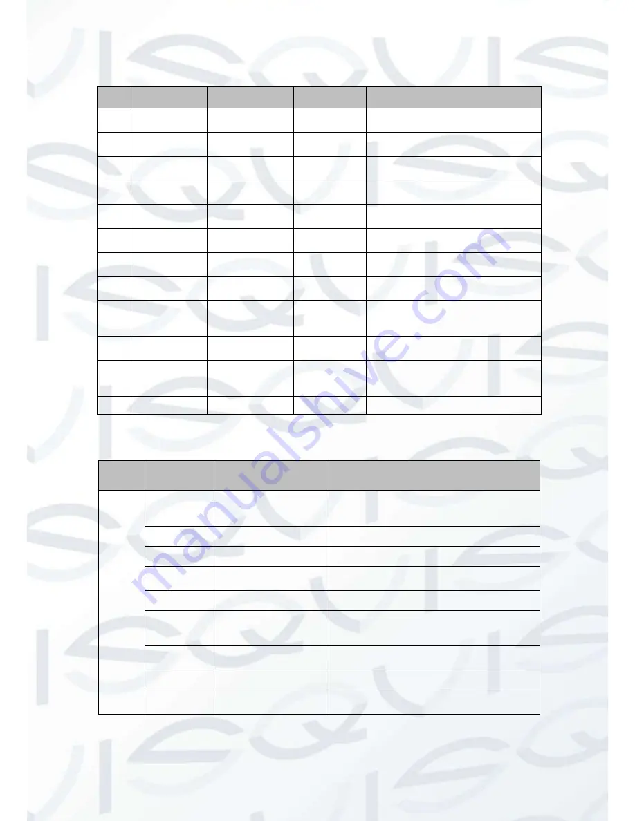
Please refer to the following sheet for external connection, specific features and port definition information: 


SN 

Port/Feature 

Port Name 

Connector 

Function Description 

POWER 

AC  24V  power 
port  

Connect to AC 24V power.  
Only some series support AC 24V. 

POWER 

DC  12V  power 
port  

Connect to DC 12V power. 

Cable exit 
hole 

Allows  power  and  Ethernet  cables 
to be accessed externally.  

LAN 

RJ45 

network 

port 

Ethernet port   Network cable port. 

I/O 

I/O port  

It includes alarm input/output, audio 
and analog output. 

RESET 

Reset button  

Reset button. It is to restore factory 
default setup.  

Toggle 
Joystick 

5-directional 
button 

Adjust  lens  focus  and  also  Auto 
Focus 

Status 
Indicator Light 

Displays camera’s running status 

Fan port 

Connect  an  internal  fan  to  reduce 
device  temperature  if  it  is  installed 
in a constantly warm location. 

 10 

Micro SD 

Micro  SD  card 
slot entry 

Micro 

SD 

card 

Connect to Micro SD card to realize 
local storage.  

11 

Power Cable  

12V Power  

This  connects  to  a  12V  DC  power 
source to power the camera if there 
is no POE switch available. 

12 

LAN Cable 

Ethernet Cable 

Connect to network. Supports PoE. 


Please refer to the following sheet for I/O port cable function information: 


Port 
Name 

Cable SN 

Cable Port Name  

Function Description  

I/O Port 

ALARM_NO 

Alarm  output  port.  Output  alarm  signal  to 
alarm device. 
NO: Normal open alarm output end.  

ALARM_COM 

Alarm output public end.  

GND 

Ground end.  

ALARM_IN 

Alarm  input  port.  It  is  to  receive  the  on-off 
signal from the external alarm source.  

GND 

Ground end.  

AUDIO_IN 

Input audio signal. It is to receive the analog 
audio  signal  from  the  devices  such  as 
pickup.  

AUDIO_OUT 

Output audio signal to devices such as loud 
speaker.  

GND 

Ground end.  

VIDEO_OUT 

Output  analog  video  signal.  It  can  connect 
to TV monitor to view video.  


Summary of Contents for AMB-VANIR

Page 1: ...AMB VANIR AMB VANIR 2 AMB VANIRM2 1 3 2 MEGA PIXEL VANDAL DOME IP CAMERAS User s Manual V2 0 06 2014...

Page 2: ...i...

Page 3: ...to be a reference tool for the installation and operation of your system Here you can find information about the corresponding IP camera s features and functions as well as a detailed installation me...

Page 4: ...ame quality if you need to return it to vendor 3 Installation Do not apply power to the product before completing installation Do not put object s on the product Please install a proper power cut off...

Page 5: ...ce You can use the dry cloth with some alcohol or mild detergent to clear if necessary When the camera is not in use please put the dustproof cap to protect the CCD CMOS component Do not use volatile...

Page 6: ...Installation Introduction 12 3 2 Device Installation Steps 13 3 2 1 General Installation 13 3 2 2 Lens pan rotation angle setup 15 3 2 3 Lens tilt rotation angle setup 15 3 2 4 Image pan rotation angl...

Page 7: ...era s field of view and is then able to filter out any visual interference so that you can easily view footage upon a monitor It supports real time monitor and listening at the same time via the inbui...

Page 8: ...Please note system cannot support these two types of power supplying at the same time As a recommendation if you wish for your security system to be able to continue to run when there is a loss of po...

Page 9: ...hite Balance Manual Auto BLC On Off DWDR Exposure Mode Manual Auto PAL ranges from 1 3 to 1 10000 Video Compression Standard H 264 MJPEG Video Frame Rate PAL Main stream 1280 960 25f ps extra stream 3...

Page 10: ...shot log email SMTP function etc Video Loss Activation event alarm device audio video storage image snapshot log email SMTP function etc Alarm Port 1 channel input and 1 channel output on off Record a...

Page 11: ...ation rights reserved 5 2 Structure 2 1 Dimensions You can refer to the following figures for dimension information The Unit is mm see Figure 2 1 Figure 2 2 Figure 2 1 Dimension illustration 1 Figure...

Page 12: ...Copyright Qvis All documentation rights reserved 6 2 2 Port Description The ports are shown in Figure 2 3 and Figure 2 4 AMB VANIR AMB VANIR2 cameras only Figure 2 3 Port 1 Figure 2 4 Port 2...

Page 13: ...Copyright Qvis All documentation rights reserved 7 The ports are shown in Figure 2 3 and Figure 2 4 AMB VANIRM2 camera only Figure 2 5 Port 2 Figure 2 6 Port 1...

Page 14: ...ce temperature if it is installed in a constantly warm location 10 Micro SD Micro SD card slot entry Micro SD card Connect to Micro SD card to realize local storage 11 Power Cable 12V Power This conne...

Page 15: ...in to the audio output port at the PC end 2 3 2 PC end to the Device end Device Connection 1 Connect the speaker or the MIC to the audio input port in the PC and then connect the earphone to the audio...

Page 16: ...se see Figure 2 5 Please set the alarm input 01 port for the first channel of the I O cable No 4 pin Then you can select the corresponding type NO NC 4 Set the WEB alarm output The alarm output 01 is...

Page 17: ...refer to the following figure for alarm output information see Figure 2 7 Port ALARM_C and Port ALARM_NO composes an on off button to provide the alarm output If the type is NO this button is normal...

Page 18: ...the dome enclosure in case it may leave marks that will obscure video image capture Before the installation please make sure the installation surface can sustain at least 3X the weight of the bracket...

Page 19: ...into the holes you have just drilled and then fix firmly If you need to drill a hole to pull through the cable you need to drill a cable exit hole on the installation surface according to the install...

Page 20: ...vice reliability For outside installation the host GND must be grounded GND of vandal proof series locates next to its exit hole Device grounding screw dimension is M3X0 5 with a valid depth of 5mm Fi...

Page 21: ...ranges from 23 73 The manual zoom lens focus interface is shown as in Figure 3 6 adjusting screws found on both motorised and non motorised cameras Figure 3 6 Lens tilt rotation angle 3 2 4 Image pan...

Page 22: ...just the lens focus to the proper position according to the displayed video Step 2 Slightly loosen the adjusting screw F and push the adjust screw F to make it swing Adjust the lens to get the clear v...

Page 23: ...f the cable exits has a M22 screw thread and can work with the default combination cable to remove the risk of the dragging and pulling of the cable Also provided are two waterproof airproof plugs One...

Page 24: ...o continue the installation Important This series product has the power connection pin and I O connection pin for you to pull through the signal cable 3 3 Micro SD Card Installation Warning Please unp...

Page 25: ...ault gateway MAC address etc Figure 4 1 Search interface Select one IP address and then right click mouse you will see an interface like the one shown in Figure 4 2 Note You can set the IP address sub...

Page 26: ...to the device web interface you can go to the configuration tool s main interface to set In the configuration tool s search interface Figure 4 1 please select a device IP address and then double click...

Page 27: ...vice If you are using device background upgrade port 3800 to login other setups are all invalid Figure 4 4 Login prompt After you logged in the configuration tool main interface is shown as below See...

Page 28: ...twork camera default IP address is 192 168 1 108 Subnet mask is 255 255 255 0 Gateway is 192 168 1 1 Use order ping network camera address to check connection is OK or not 5 2 Login and Logout 1 Open...

Page 29: ...or not after you have logged in for one minute Please click OK button the system can automatically install the control When system is upgrading it can overwrite the previous Web as well If you can t d...

Page 30: ...Copyright Qvis All documentation rights reserved 24 After you logged in you can see the main window See Figure 5 4 Figure 5 4 Web monitoring window...

Page 31: ...nue upgrade I cannot login the client end or the WEB The Active X control is blocked The display card version needs to be DX8 1 or higher Network connection error occurred Invalid network setup Invali...

Page 32: ...hts reserved 26 For more information about our IP Cameras and other available cameras NVRs accessories please visit our website www adata co uk Alternatively scan this QR code with your smart phone to...

Reviews: