background image

10

QUIETCOOLSYSTEMS.COM

4. 

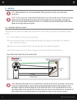
Mount the thermostat in the best location for thermostat readings. Run a 2 wire Romex from the 
junction box to the thermostat. Tape the white wire on each side of the 2 wire Romex to indicate that 
it is a switch leg. 

5. 

In the junction box, with a wire nut, tie the white common wires together. Using the green ground 
screw, ground the green wire from the fan and the 2 wire Romex from the thermostat, to the junction 
box. Tie the black wire from the fan to the taped white wire from the thermostat. Tie the black wire 
from the power source to the black wire from the thermostat. Replace the cover on the junction box. 

6. 

In the themostat, tie the black wire to one of the black wires from the thermostat. Tie the taped wire 
to the other black wire from the thermostat. Using the ground screw in the thermostat, ground the 
ground wire from the 2 wire Romex. 

3.3  Specialty Fan Wiring - Timer

For wiring of a Specialty Series Fan with a timer. This wiring method works with all of our Specialty Series fans. 

1. 

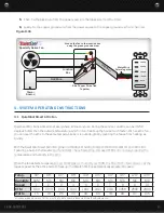
For this installation, you will need a 2 & 3 wire Romex, and an 8 Hour Timer. 

2. 

Begin wiring the timer. From your 3 wire Romex, using a wire nut, tie the two red wires together, the 
two white wires together, the two black wires together, and the two ground wires together.

3. 

Open up the junction box that is connected to the fan. Bring your 2 wire and 3 wire into the junction 
box. 

3. 

Tie the white common wires from the fan, the power source, and the timer together. Then, using the 
green ground screw, ground the green wire from the fan to the handy box. 

4. 

With a wire nut, tie the black wire from the fan to the red wire from the timer. 

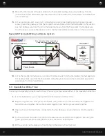
Figure 3.2B: Thermostat Wiring in a Remote Location

Ground the fan to the junction box 

using the green ground screw

Specialty Series Fan

Junction

Box

Power Source

14-2 Wire

14-2 Wire

14-2 W

ire

60°

Thermostat

FAN ON

TEMPERATURE

90°

120°

®

ADJUSTABLE

TEMPERATURE THERMOSTAT

CAUTION

Automatically started device - to reduce the

risk of injury disconnect from power supply

before servicing.  For residential use only.  See

instructions for wiring diagram.

60°

ADVANCED ATTIC GABLE FANS

®

Summary of Contents for AFG SMT-3.0

Page 1: ...SEE HEAR FEEL THE QUIETCOOL DIFFERENCE ADVANCED WHOLE HOUSE FANS THE NATURAL CHOICE FOR ENERGY SAVINGS INSTALLATION GUIDE SPECIALTY SERIES FANS...

Page 2: ...em The user should not attempt to service the product 7 Building Codes Always follow Local Building Codes when installing appliances CONTENTS 1 SYSTEM OVERVIEW 1 1 1 Introduction 1 1 2 Features 1 1 3...

Page 3: ...ergy efficient too We also have the AFG PRO 3 0 the most powerful residential attic fan on the market QuietCool Garage Fans The QuietCool Garage Fans offer great ventilation options for your garage ma...

Page 4: ...1 SQUARE FOOT OF NET FREE VENT AREA PER 750 CFM RECOMMENDED 2 TO 4 SQUARE FEET OF INLET VENTS PER FAN Vent Type Model Type Average Size Venting Sq Ft Gable vent 12 x 19 5 1 20 Dormer Vent 14 x 8 0 70...

Page 5: ...an be mounted flush to a rectangular type louver by fastening through the mounting brackets to the frame of the louver as shown in Figure 2 1A As stated in the note above any area of the louver that i...

Page 6: ...to install your QuietCool Garage Attic Fan Now it s time to find the exact location using a stud finder Locate the ceiling studs and mark the location for the fan to be installed see Figure 2 2A One s...

Page 7: ...l saw cut out the opening Remove the drywall cutout and clear away insulation if applicable see Figure 2 2C 4 From the interior drill a hole through the exterior at the four corners of the cut out see...

Page 8: ...utting the roof If you are installing the RM ES 1100 mark a 14 1 4 x 14 1 4 square If you are installing the RM ES 2200 mark a 16 1 4 x 16 1 4 square see Figure 2 4A 3 Move to the roof and using a cir...

Page 9: ...level of the fan NEVER install the ceiling grille directly underneath the fan Always offset at least two feet Figure 2 4A Figure 2 4B Figure 2 4C Figure 2 4D Roof Mount Application Diagrams Flat Roof...

Page 10: ...t tie the white common wire together Then tie the black wires together 4 Ground the green wire from the fan and the ground wire from the Romex to the junction box NOTE When the Smart Attic Fan is conn...

Page 11: ...ex junction box and a thermostat 2 Open up the thermostat that is connected to the fan Remove the power cord Remove the bracket mounting the thermostat to the flex tubing and remove the thermostat 3 M...

Page 12: ...two red wires together the two white wires together the two black wires together and the two ground wires together 3 Open up the junction box that is connected to the fan Bring your 2 wire and 3 wire...

Page 13: ...ic When the fan detects temperature over 80 degrees or humidity over 60 the Smart Attic Fan comes on at the lowest speed As the attic starts to heat up the Smart Attic Fan automatically adjusts it s s...

Page 14: ...uced the heat transfer between the attic and garage on really hot days Our GX ES 1100 works well to cool and ventilate your garage Run both of these fans when it is cooler outside than it is in your g...

Page 15: ...the original date of purchase C This warranty does not cover any of the following 1 Incidental or consequential damage resulting from the operation of our equipment or any malfunction thereof 2 Cost...

Page 16: ...14 1 888 QUIETCOOL ADVANCED WHOLE HOUSE FANS QuietCool is Proudly Designed and Built in California 43352 Business Park Drive Temecula CA 92590 PH 951 325 6340 QUIETCOOLSYSTEMS COM...

Reviews: