25
Quicksilver 675WE —
System & Component Overview and Operation
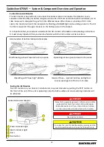
Tank Level
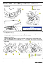
Located in the battery switch panel tub, there is a gauge for reading the level of fluid in the holding
tank. To see how much fluid is in the holding tank, press the momentary switch towards Tank 2.
Dockside Pumpout
The dockside pumpout deck plate is located on the starboard side deck trail, and is marked with the
ISO symbol WASTE. The dockside facility will have the proper connections / fittings to pump the grey
water tank out.
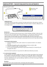
Macerator (optional)
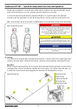
The optional macerator gives the boat operator the means of discharging the grey water tank directly
overboard through a seacock in the bottom of the hull. The macerator control is located on the main
battery panel in the starboard battery panel tub labelled
“
Waste pump
2”.
Since direct overboard
discharge is prohibited in many areas, the macerator seacock is normally closed.
To Operate the Macerator:
1.
Make sure the macerator seacock is in the open position.
2.
Press and hold the macerator switch located on the main battery panel. The macerator switch
is a momentary switch, which means that it needs to be pressed during operation.
The dockside pumpout deck plate does not have a chain
connecting the cap to the deck plate. Use caution not to
drop the deck plate cap into the water.
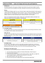
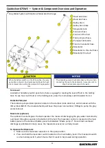
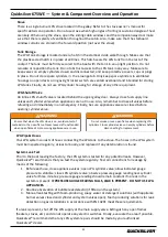
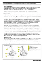
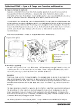
Grey Water System with Optional Macerator Discharge
Head sink drain
Head sink hose
Galley drain
Galley drain hose
Greywater tank
Tank vent hose
Tank vent thru hull
Tank pumpout hose
Pumpout deck plate
Tank to macerator hose
Macerator
Macerator to thru
-
hull hose
Macerator thru
-
hull
When the battery switch is in the OFF position, the sump
pump does not work. Any liquids poured down the head
sink or shower drain will not be pumped to the grey water
tank.
Summary of Contents for 675WE
Page 1: ...675WE Owner s Manual...
Page 2: ......
Page 16: ...Quicksilver 675WE General Information 4 6 Safety Label Locations Cockpit Bilge Exterior...
Page 18: ...Quicksilver 675WE General Information 6 Safety Label Locations Helm...
Page 62: ...Quicksilver 675WE Electrical Systems 50 DC Wiring Schematic...
Page 63: ...Quicksilver 675WE Electrical Systems 51 Bow Thruster Schematic Bow Windlass Schematic...
Page 64: ...Quicksilver 675WE Electrical Systems 52 AC Power Schematic...
Page 69: ...Quicksilver 675WE Specifications 57 LMAX LH BH BMAX TH TMAX Ha LMAX OPTION...
Page 70: ...Quicksilver 675WE Specifications 58...
Page 90: ......


