119832 Rev. B
29
E N G L I S H
QUICKIE PULSE
IX.
G. COLOR LCD SCREEN
This section covers those joystick modules that are fitted with a color LCD screen. The
color LCD screen is split into three areas of information. The Top Bar, the Base Bar and the
Main Screen Area.
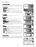
1. Top Bar (Fig. 1 & 2)
Battery Indicator (Fig. 2): Displays the charge available in the battery and can be used to
alert the user to the status of the battery.
Steady: Indicates that all is well.
Flashing Slowly: The control system is functioning correctly, but you should charge the bat-
tery as soon as possible.
Stepping Up: The wheelchair batteries are being charged. You will not be able to drive the
wheelchair until the charger is disconnected and you have switched the control system
off and on again.
2. Base Bar (Fig. 3)
Current Profile: The currently selected profile is shown in numeric form.
3. Main Screen Area
Drive Screen
Profile Name (Fig. 4): This is a text string that displays the name of the currently selected
profile.
Clock (Fig. 5): This displays the current time in a numeric format.
Speed Display (Fig. 6): This gives a proportional display of the wheelchair’s speed.
Maximum Speed Indicator (Fig. 7): This displays the current maxiumum speed setting.
Digital Speed Display (Fig. 8): This displays the actual speed of the wheelchair derived
from the motors.
Inhibit (Fig. 9): If the speed of the wheelchair is being limited; for example, by a tilted seat,
then this orange symbol will be displayed.
Mode Screens
Actuator Mode (Fig. 10): Displays the sections of the chair currently selected for move-
ment, the name given to the selection and a direction arrow showing what sort of
movement is available.
Speed Adjust (Fig. 11): When Speed Adjust Mode is entered, the following screen shown in
Figure 11 will be displayed.
Message Window (Fig. 12): The RNET displays warning icons and informational messages,
in a dedicated message window.
Restart (Fig. 13): When the control system requires a reboot; for example, after a module
re-configuration, this symbol will be flashed.
Timer (Fig. 14): This symbol is displayed when the control system is changing between dif-
ferent states. An example would be entering into Programming Mode. The symbol is
animated to show the sands falling.
Diagnostic Screen (Fig. 15)
When the control system safety circuits have operated and the control system has been pre-
vented from moving the wheelchair, a diagnostics screen will be displayed. This indicates a
system trip, i.e. the RNET has detected a problem somewhere in the wheelchair’s electrical
system.
1.55 mph
14:35
1
Indoor-drive
1
3
4
5
2
6
9
7
10
11
12
14
13
15
8

