Quantum TC2201E Installation Instructions Manual Download Page 8

Quantum TC2201E Installation Instructions
Document 81-81449-01 A01
July 2005

8

Connecting the TC2201E

Connecting the TC2201E

0

There are four types of interfaces to the TC2201E:
• iSCSI 
• SCSI 
• RS-232 (3-pin Serial) [Management/Configuration Interface]
• Ethernet [Management/Configuration Interface]

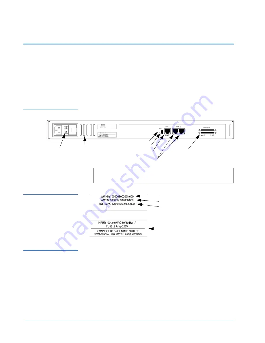
Figure 6  Port locations

Air-exhaust

Vents

SCSI buses

iSCSI ports

Ethernet port

Serial port

Reset Button

Power

switch

Note:

For convenience in configuring ports, key information is 

indicated on a label located on the back panel of the TC2201E.

Figure 7  WWN/MAC ID 
label

WWN Name

WWP Name

Ethernet MAC ID (Physical Address)

Power Information

iSCSI Connections

0

Before connecting the TC2201E to other iSCSI devices, it is important to 

understand the configuration requirements of the environment to which it 

will be connected. Failure to correctly configure an iSCSI device may impair 

the operation of the network to which it is attached. 
The iSCSI RJ-45 connectors on the unit can be directly connected to a standard 

10/100/1000BaseT Ethernet network.
Typical installations will have the TC2201E connected to an Ethernet switch 

or hub. The unit can also be directly attached to the iSCSI host bus adapter, in 

a Point-to-Point fashion. 

Summary of Contents for TC2201E

Page 1: ...the TC2201E on a Desktop 4 Installing the TC2201E in a Rack 4 Required Tools 4 Installing the TC2201E With Ear Brackets 4 Connecting the TC2201E 8 iSCSI Connections 8 SCSI Connection 9 Ethernet Manag...

Page 2: ...Quantum TC2201E Installation Instructions Document 81 81449 01 A01 July 2005 2...

Page 3: ...ing alternate hardware may cause damage to the unit Installing the TC2201E consists of the following steps Choosing a Location Unpacking the Box Installing the TC2201E on a Desktop Installing the TC22...

Page 4: ...he TC2201E on a table or desktop 1 Remove the TC2201E from the protective bag 2 Attach the stick on feet to the bottom of the unit 3 Place the TC2201E on the table or desktop Installing the TC2201E in...

Page 5: ...take exhaust vents remain clear of obstructions to ensure proper airflow 3 Remove any blanking panels and other equipment from the chosen rack location 4 Install the cage nuts on the vertical mounting...

Page 6: ...ore information Tighten the screws securely Figure 3 Attaching the Ear Brackets 7 If you are mounting the TC2201E in the rack with the ports facing inside the rack shown in Figure 2 4 or with the port...

Page 7: ...ions Document 81 81449 01 A01 July 2005 Installing the TC2201E in a Rack 7 Figure 4 Mounting at front of rack Figure 5 Mounting at Back of the Rack Once the TC2201E is installed you are ready to conne...

Page 8: ...k panel of the TC2201E Figure 7 WWN MAC ID label WWN Name WWP Name Ethernet MAC ID Physical Address Power Information iSCSI Connections 0 Before connecting the TC2201E to other iSCSI devices it is imp...

Page 9: ...TC2201E powered off connect the TC2201E into the iSCSI environment using the appropriate cabling Be sure to insert the cable connectors in the proper orientation SCSI Connection 0 The TC2201E can sup...

Page 10: ...Power off the TC2201E whenever connecting disconnecting the SCSI cables Any SCSI cables used with the TC2201E series product must meet SCSI 2 standards and must be LVD rated specifically low noise cab...

Page 11: ...Connection 0 10 100BaseT Ethernet connectivity provides enhanced management and configuration capabilities The RJ 45 connector on the unit can be directly connected to a standard 10 100BaseT Ethernet...

Page 12: ...E turned off until you have set up the serial port communications on your host computer unless serial I O was previously established and is currently running The TC2201E is designed to communicate wit...

Page 13: ...o Sensing but the correct type of power cable needed for your installation should still be verified The power cable shipped with the TC2201E is a 120 VAC 3 conductor power cable for use in the United...

Page 14: ...baud rate Once the POST and firmware initiation processes are complete the main menu should be accessible over the serial port Optionally the main menu can also be accessed over the Ethernet port as d...

Reviews: