10
Installing the DXi6701 or DXi6702 System
DXi6701/DXi6702 Installation and Configuration Guide
Installing the DXi6701 or DXi6702 System
Installing the DXi6701/DXi6702 in a rack consists of the following steps:
1
Locating the Mounting Position
2
Installing the DXi6701 and DXi6702 Node
3
Installing the DXi6701 and DXi6702 Expansion Module
4
Locating the Mounting
Position
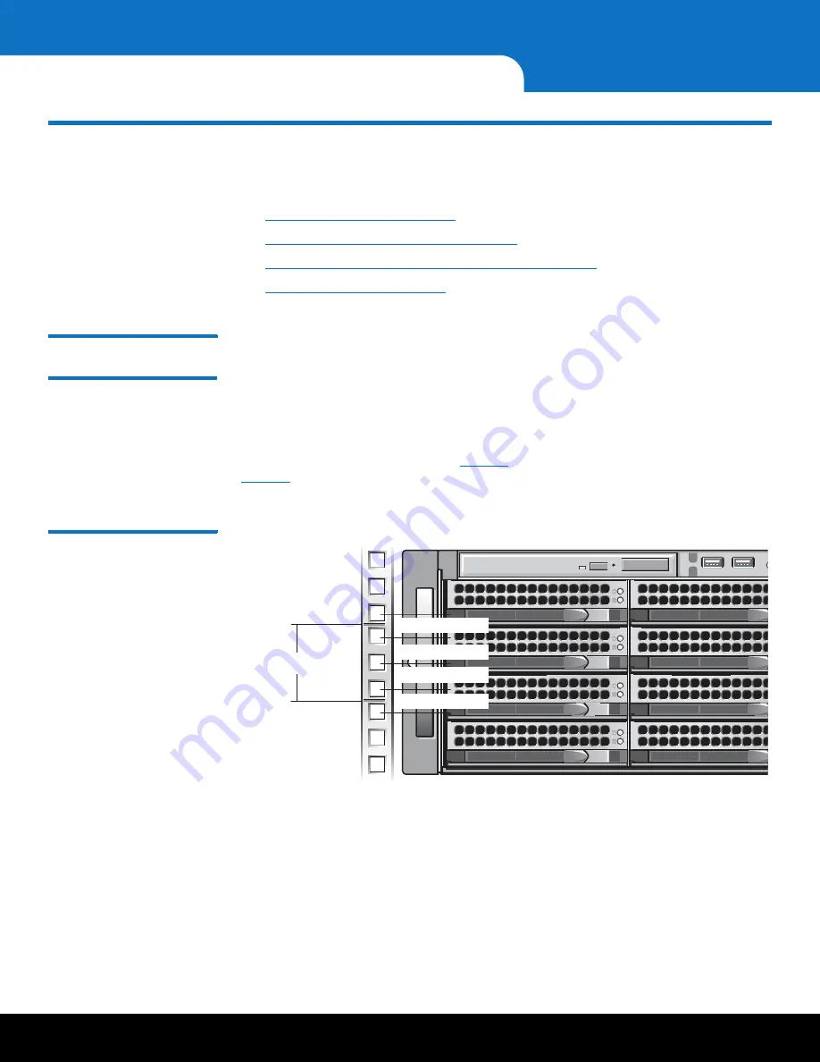
The DXi6701/DXi6702 systems is designed to fit in a standard 19 inch wide rack. It is
important for the chassis installation to locate the hole pattern in the rack rails. You
must allow 3U (5.2 in. / 13.2 cm) of vertical space for the DXi6701 and DXi6702 node
and 2U (3.5in. / 8.9 cm) of vertical space for each expansion module installed in the rack.
Rack cabinets that meet EIA-310 standards have an alternating pattern of three holes
per rack unit with center-to-center hole spacing (beginning at the top hole of a 1U
space) of 15.9 mm, 15.9 mm, and 12.7 mm (0.625 inch, 0.625 inch, and 0.5 inch) for
the front and back vertical rails (see
for the DXi6701 and DXi6702 node and
for the expansion module). Rack cabinets may have round or square holes. For
more information, refer to the
DXi6701 and DXi6702 Site Planning Guide
(PN 6-67200).
Figure 3 Rail Hole Pattern
(DXi6701/DXi6702 Node)
1 U (44 mm [1.75 inches])
12.7 mm (0.5 inch)
15.9 mm (0.625 inch)
15.9 mm (0.625 inch)
12.7 mm (0.5 inch)


