NWA-6500 Series - User Guide, Rev. 1.4
// 52
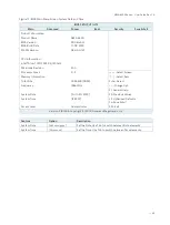
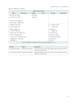
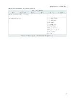
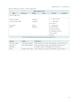
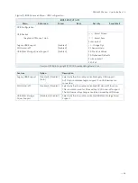
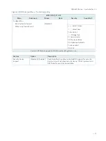
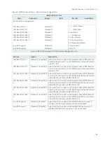
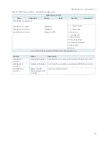
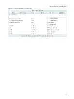
Figure 15: BIOS Advanced Menu - FIA HSIO10 Configuration
BIOS SETUP UTILITY
Main
Advanced
Power
Boot
Security
Save & Exit
Flexible I/O Adapter HSIO10 Configuration
HSIO10 I/O amount
Full Avtive
Lane 8: PCIE-C6139 (VGA)
[PCIE Enabled]
Lane 18: XHCI-A
[XHCI Enabled]
Lane 19: XHCI-B
[XHCI Enabled]
→
←
: Select Screen
Lane 0: I210-AT-1
[PCIE Enabled]
↑
↓
: Select Item
Lane 2: I210-AT-2
[PCIE Enabled]
Enter: Select
Lane 10: mPCIE1 / mSATA
[JP5 with mPCIE]
+/-: Change Opt.
Lane 4: M.2 Key-A
[PCIE Enabled]
F1: General Help
Lane 6: M.2 Key-B (SATA)
[JP4 with PCIE]
F2: Previous Values
Lane 9: SATA1
[SATA Enable]
F3: Optimized Defaults
F4: Save & Exit
SIM Switch Control
[To mPCIE1]
ESC: Exit
Version 2.19.1266. Copyright (C) 2018, American Megatrends, Inc.
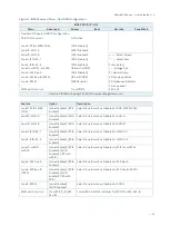
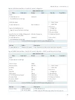
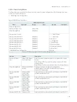
Feature
Option
Description
Lane 8: PCIE-C6139
(VGA)
[Lane Disabled], [PCIE
Enabled]
Select Lane to work as Disabled or PCIE-C6139 (VGA).
Lane 18: XHCI-A
[Lane Disabled], [XHCI
Enabled]
Select Lane to work as Disabled or XHCI-A.
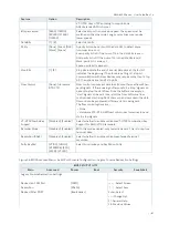
Lane 19: XHCI-B
[Lane Disabled], [XHCI
Enabled]
Select Lane to work as Disabled or XHCI-B.
Lane 0: I210-AT-1
[Lane Disabled], [PCIE
Enabled]
Select Lane to work as Disabled or I210-AT-1.
Lane 2: I210-AT-2
[Lane Disabled], [PCIE
Enabled]
Select Lane to work as Disabled or I210-AT-2.
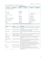
Lane 10: mPCIE1 /
mSATA
[Lane Disabled], [PCIE
Enabled], [SATA
Enabled], [JP5 with
mPCIE]
Select Lane to work as Disabled, mPCIE1 or mSATA1.
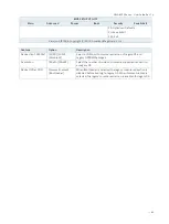
Lane 4: M.2 Key-A
[Lane Disabled], [PCIE
Enabled]
Select Lane to work as Disabled or M.2 Key-A.
Lane 6: M.2 Key-B
(SATA)
[Lane Disabled], [PCIE
Enabled], [SATA
Enabled], [JP4 with
PCIE]
Select Lane to work as Disabled or M.2 Key-B (SATA).
Lane 9: SATA1
[Lane Disabled],
[SATA Enabled]
Select Lane to work as Disabled or SATA1.
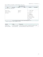
SIM Switch Control
[To mPCIE1], [To M2
Key-B]
Control Micro SIM Card Holder for MPCIE1 or M2_KEY-B.


